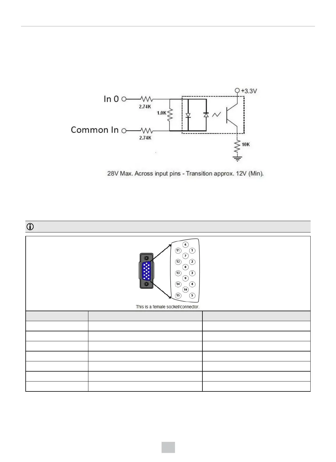
Acquisition Triggering
To trigger from an NPN (pull-down) type photo-detector or PLC output, connect Common In to +24VDC and connect In 0
to the output of the detector. When the output turns on, it pulls Common In down to 0VDC, turning the opto-coupler on.
To trigger from a PNP (pull-up) type photo-detector or PLC output, connect to the output of the detector and connect to
0VDC. When the output turns on, it pulls up to 24VDC, turning the opto-coupler on.
I/O Cable
You can connect a cable with USB & flying leads (DM-USBIO-00) to the cable that is attached to the device. The
following table shows the pinout and color description of the flying leads.
Note: GND (Pin 4) is connected to the reader housing, cable shield, and DB15 shell.
PIN Color Signal
4 Black GND
7 Blue/White Output-0
8 White Input-0
9 White/Black Input-1
11 Light Blue/Black Output-1
12 Light Blue/Yellow Output-Common
13 Light Blue/Green Input-Common
35
 Loading...