Pre-Installation Guidelines & Checklist
9
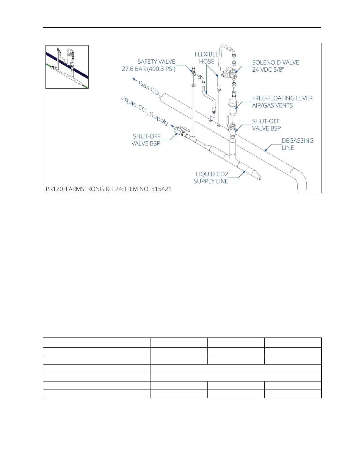
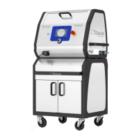
Figure 3: Degasser (Armstrong) Kit
The Degasser (Armstrong) kit will need to be integrated into the production system by the
customer's piping contractor.
Gas CO
2
Exhaust System
An exhaust pipeline with an internal diameter greater than 2.5 inches is installed to facilitate
the exhaust CO
2
gas from the dry ice production process. The exhaust CO
2
gas must be vented
at a safe location outside of the building with a weatherproof outlet that prevents rainwater or
other contaminants from blocking or creating back-pressure to the pelletizer.
Additionally, the CO
2
exhaust could have a temperature as low as -27°C (-16.6°F) which may
generate condensation. Cold Jet recommends installing an Armaex insulation or similar
product to prevent this condensation from dripping down onto the machine or production
room oor.
Gas CO
2
Exhaust System PR120H PR350H PR750H
Gas CO
2
Exhaust Volume 132 kg/hr (291 lb/hr) 385 kg/hr (489 lb/hr) 825 kg/hr (1819 lb/hr)
Gas CO
2
Exhaust Volume (Standard Conditions) 77 N·m
3
/hr 224 N·m
3
/hr 481 N·m
3
/hr
Operating Design Gas CO
2
Pressure (PRV) 1 barg (14.5 psig)
Max Allowable Back-Pressure < 1.0 bar (< 14.5 psi)
Gas CO
2
Line Size Minimum ID 50 mm (2 in) 63.5 mm (2.5 in) 63.5 mm (2.5 in)
Gas CO
2
Connection at Pelletizer (Welding Stud) 50 mm (2 in) 63.5 mm (2.5 in) 63.5 mm (2.5 in)