IS-NT-Async-SPI, SW Version 1.2, ©ComAp – February 2011
IS-NT-Async-SPI-1.2.PDF
78
GCB open del [ s ] (FV)
The timeout to unload the gen-set. Should the load ramp fail to bring the gen-set power down to GCB open
level to allow the opening of GCB, the breaker will open after GCB open del.
Step: 1 s
Range: Load ramp – 1800 s
Force value possibility: Yes
GCB close TOut [s]
Maximum allowed time for RPM matching procedure.
Step: 1 s
Range: 1 – 1800 s, NO TIMEOUT
RPM matching /load control adjustment
Hint:
Use isochronous speed governor.
Two wire shielded connection from controller SPEED GOVERNOR output (SG OUT, SG COM) to Speed
governor auxiliary input is recommended.
A full range change of the IS speed governor output (from –10V to 10V) should cause 5-10% change of the
engine speed (-10V ~ 95% RPM
nom
, 0V ~ 100% RPM
nom
, +10V ~ 105% RPM
nom
IMPORTATNT
Speed governor has to be adjusted for optimum performance before controller RPM match / load
control adjusting.
Check generator phase sequence before the first GCB connection.
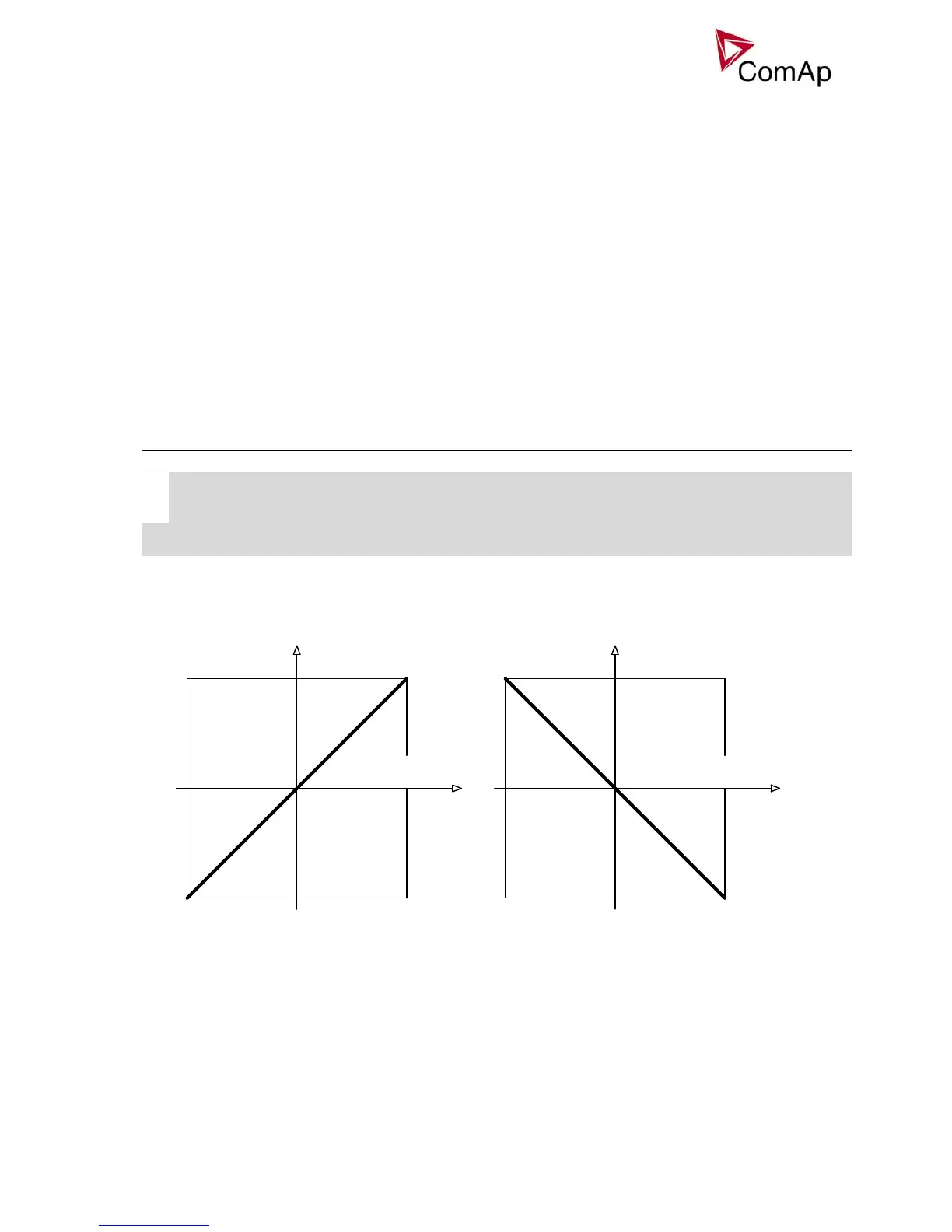
RPMRPM
Volt [V] Volt [V]
0 V
+10 V- 10 V
Speed governor
voltage output1500
50
1575 RPM
52.5 Hz
1425 RPM
47,5 Hz
0 V
- 10 V
1500
50
1575 RPM
52.5 Hz
1425 RPM
47,5 Hz
+10 V
Speed governor
voltage output
+ 2.5 % of nominal+ 2.5 % of nominal
- 2.5 % of nominal - 2.5 % of nominal
SpeedRegChar = POSITIVE SpeedRegChar = NEGATIVE
Before optimalization of RPM/Load ctrl setpoint group adjusting disconnect GCB OPEN/CLOSE output or
set RPM matching = 0 to avoid paralleling.
RPM matching adjustment
1) Start the engine in MAN Mode.
2) Set the engine RPM by speed trim on speed governor or by Speed gov bias and SpeedGovLowLim
to Nominal frequency.