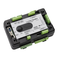
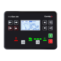
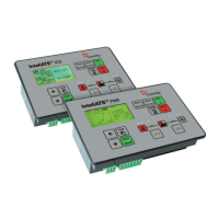
InteliGen
NT
, InteliSys
NT
, InteliMains
NT
– Troubleshooting Guide,
SW version IGS-NT-3.1.0, IM-NT-3.1.0, ©ComAp – August 2018 32
IGS-NT Troubleshooting Guide.pdf
IGS-NT Alarm/History
record
Alarm/
History
Appeara
nce
NotReady state is shown on the controller screen and the
message appears in the Alarm list. As soon as input is
deactivated, engine start is enabled again.
Warning protection on AI Cylinder temperature 1-32 is
active. Check corresponding setpoints in the Engine
protect group.
MCB failure was detected.
See Circuit breakers operation sequence, GCB/MCB fail
detection chapter in IGS-NT-x.y-Reference Guide.
GCB failure was detected.
See Circuit breakers operation sequence, GCB/MCB fail
detection chapter in IGS-NT-x.y-Reference Guide.
BTB failure was detected.
See Circuit breakers operation sequence, GCB/MCB fail
detection chapter in IGS-NT-x.y-Reference Guide. It
applies to BTB breaker too.
MGCB failure was detected.
See Circuit breakers operation sequence, GCB/MCB fail
detection chapter in IGS-NT-x.y-Reference Guide. It
applies to MGCB breaker too.
Engine shut-down was activated by binary input with “Oil
press” function (see LBI card in GenConfig for information
about source signal for this function).
Reverse synchronization failure indication, genset or group
of gensets was not synchronized to mains within
Sync/Load ctrl:Sync timeout time.
Check setting of setpoints in the Sync/Load ctrl and
Volt/PF ctrl groups. Frequency regulation loop, Angle
regulation loop and Voltage regulation loop are active
during synchronisation and you may need to adjust their
setting.
Actual state of synchronization is visible on the controller
measurement screen with synchroscope where speed and
voltage regulator's outputs, slip frequency and generator
and mains voltages can be observed during the
synchronization process.
Synchronization failure indication (alarm Sync timeout is
active), gen-set or group of gensets was not synchronized
to mains/bus within Sync/Load ctrl:Sync timeout time.
Check setting of setpoints in the Sync/Load ctrl and
Volt/PF ctrl groups. Frequency regulation loop, Angle
regulation loop and Voltage regulation loop are active
during synchronisation and you may need to adjust their
setting.
Actual state of synchronization is visible on the controller
measurement screen with synchroscope where speed and
voltage regulators' outputs, slip frequency and generator
and mains/bus voltages can be observed during the
synchronization process.
Synchronization failure indication (alarm Sync timeout is
active), gen-set or group of gensets was not synchronized
to mains/bus within Sync/Load ctrl:Sync timeout time.
Check setting of setpoints in the Sync/Load ctrl and
Volt/PF ctrl groups. Frequency regulation loop, Angle
regulation loop and Voltage regulation loop are active
 Loading...


