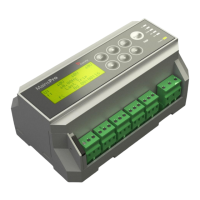
MainsPro, SW version 1.4, ©ComAp – January 2013
MainsPro Application Guide
Protective features
The following protective functionalities, referred also by their ANSI number, are available in MainsPro
unit:
ANSI 59 Overvoltage, ANSI 27 Undervoltage
The RMS value of measured voltage is compared with the preset limit of overvoltage or undervoltage.
When any of the preset limits is over/underreached, the appropriate LED signal is issued by LED U
and the output U Sig moves to fault-indicating position immediately. If voltage of in the given phase
keeps out of limits for the delay of the appropriate stage, TRIP is issued. As the voltage returns back
within limits in all measured phases, the LED and U Sig output stop to signal the fault state
immediately, regardless of whether TRIP was issued or not or Fault reset was performed or not.
Both overvoltage and undervoltage protective stages provide possibility of setting 2 levels with
independent delay assigned to each level.
Floating 10 minutes average overvoltage
The unit calculates floating average of the measured voltage in each phase over 10 minutes interval. If
any of the three phase values overreaches the setpoint V<> : Avg V>, TRIP is issued, LED U
flashes and counter of voltage disturbances is incremented. As the Last Trip record, the message
"Vavg" is displayed. The protection stage is blocked for the first 10 minutes after power-up of the unit.
ANSI 81H Overfrequency, 81L Underfrequency
The frequency value measured on phase L1 is compared with the preset limit of overfrequency or
underfrequency. When any of the preset limits is over/underreached, the appropriate LED signal is
issued by LED f and the output f Sig moves to fault-indicating position immediately. If the frequency
keeps out of limits for the delay of the appropriate stage, TRIP is issued. As the frequency returns
back within limits, the LED and f Sig output stop to signal the fault state immediately, regardless of
whether TRIP was issued or not or Fault reset was performed or not.
Both overfrequency and underfrequency protective stages provide possibility of setting 2 levels with
independent delay assigned to each level.
Note: MainsPro measures frequency on the phase L1 only, therefore frequency measurement will be
distorted in case that a fault occurs in this phase.
ANSI 47 Voltage unbalance and angle asymmetry
MainsPro provides 3 independent methods for evaluation of voltage symmetry failures. All of these
protections are only active in case that 3-phase system is selected by the setpoint Basic: System.
Voltage unbalance
In further text, this term refers to the state, when amplitude difference between any 2 phases
overreaches the preset limit dU: V unb. I.e., it refers to the amplitude unbalance of the measured
voltage.
Positive sequence undervoltage, Negative sequence overvoltage
These two methods provide very good sensitivity also to angle asymmetry of the measured voltages.
The evaluation is based on the mathematical principle of evaluation of the symmetrical components of
measured voltage. Any 3-phase system in any asymmetrical arrangement may be decomposed to 3
perfectly symmetrical components:
positive sequence - system of 3 phases with 120° phase-shift between the system vectors and
the same phase-order as the original system.
negative sequence - system of 3 phases with 120° phase-shift between the system vectors
and opposite phase-order as the original system.
zero sequence - system of 3 conphase vectors (with 0° phase-shift between the phases).

 Loading...