MainsPro, SW version 1.4, ©ComAp – January 2013
MainsPro Installation and Operation Guide
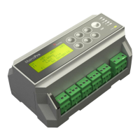
List of terminals
Binary inputs – COM terminal
Configurable binary inputs
First set of voltage measurement terminals (U
A
).
Terminals U
A
1 and U
A
2 are internally interconnected
Second set of voltage measurement terminals (U
B
).
Terminals U
B
1 and U
B
2 are internally interconnected
Third set of voltage measurement terminals (U
C
).
Terminals U
C
1 and U
C
2 are internally interconnected
RE1-5 relay contact – common
RE1-5 relay contact – normally closed (during fault-
free conditions maintained in open position)
RE1-5 relay contact – normally open (during fault-
free conditions maintained in closed position)
Power supply – high range 85-265 VAC / 110 – 370
VDC
Power supply – low range 8 – 40 VDC. Connect “+”
pole to this terminal
Common terminal for power supply. In case of DC
supply, connect “–“ pole to this terminal
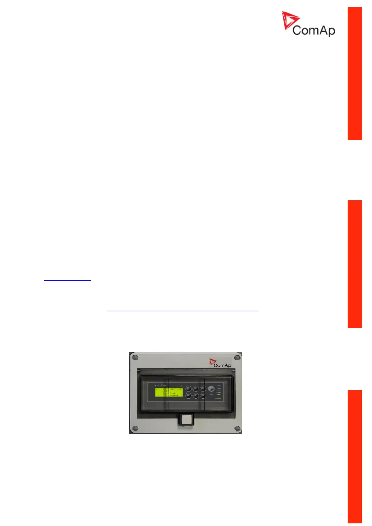
MainsPro Frame
MainsPro Frame is a MainsPro accessory product, allowing door-mounting of the unit, direct access to
the keyboard and the screen without opening the switchboard, and additional shielding (IP 55) for the
front panel. The frame size is 230x180x34 mm.
For further details visit http://cdn.comap.cz/files/other/Ramecek_MainsPro.jpg