INSTANCE 2
• SyStem wIth SImplebuS addreSSeS In
progressive order with initial address
other than 1
} Apply label 1 to the internal unit
with a Simplebus which is the
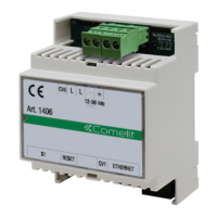
same as the S1 DIP-switch for
art. 1406.
Example 51
} Apply the user booklet with the same index as
the label to the internal unit, or hand it to the user
in the apartment in person.
} Continue progressively for all apartments.
Label 1 Internal unit 51
Label 2 Internal unit 52
Label 3 Internal unit 53
…
Label 50 Internal unit 100
Warning! Use the System Data form as an installation
guide, to make sure the label and the Simplebus
address match. The bottom of the label showing the
internal unit microswitch configuration is no longer
valid for double checking. Use the addresses table on
page 28 to check the position of the microswitches
on the internal units.
INSTANCE 3
• SyStem wIth SImplebuS addreSSeS In non-
progressive order
} Apply the labels using the System Data form as a
guide and make sure the label and the Simplebus
address match.
} Apply the user booklet with the same index as the
label to the internal unit, or hand it to the user in the
apartment in person.
The system management portal can be used to
print the apartment configuration applied,
showing the correspondence between the
Simplebus address and the Index value shown
on the labels so that they can be installed
correctly on door-entry phones or door entry
monitors.
Configuring SimpleApp - user’s responsibility
} Scan the QR code to download SimpleApp directly.
} Log into your Comelit account or register a new
account.
} Scan the QR code again to link the account with
the art. 1406.
Reboot with predetermined network settings
This procedure is used to restart the module with the
default network parameters.
In the event of a further restart the module:
• will restore the parameters from the previous
configuration, if the user has not made any
changes;
• will start up with the new network parameters,
if the parameters have been changed using ViP
Manager.
} DIP-switches set to OFF
1. Cut o the device power supply
2. Set DIP1 to ON
3. Restore the device power supply
4. Wait for approximately 20-40 sec., until the LEDs
flash slowly and alternately (1 sec. red / 1 sec.
green)
5. Set DIP1 back to OFF
» The green LED will flash for 5 sec.
» The device will start with the default network
settings.
• The saved parameters will be recovered at a
subsequent device restart process.
Factory reset
This procedure is used to restore all the parameter
values to their factory settings, and to clear all device
configurations.
} DIP-switches set to OFF
1. Cut o the device power supply
2. Set all DIP-switches to ON
3. Restore the device power supply
4. Wait for approximately 20-40 sec., until the LEDs
flash rapidly and alternately (0.1 sec. red / 0.1 sec.
green)
5. Set the DIP-switches back to OFF
›› The red LED will flash for 5 sec.
›› The device will restart.
EN
10
 Loading...