3
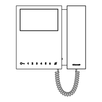
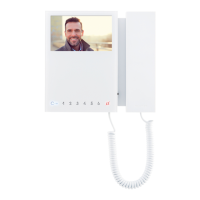
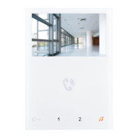
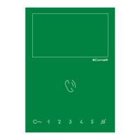
Description of the monitor
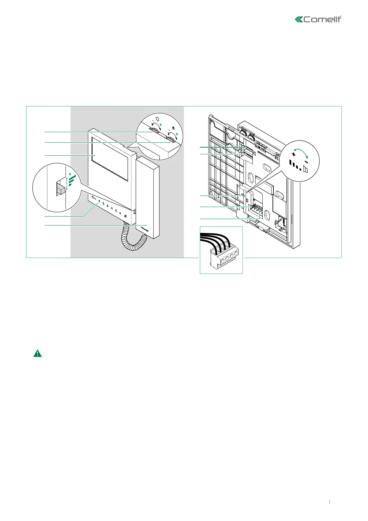
L
L CFP1
CFP2
1. Brightness control
f To increase the value, turn clockwise
2. Colour intensity adjustment
f To increase the value, turn clockwise
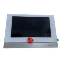
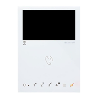
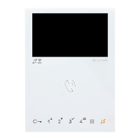
3. 4.3" colour LCD screen
4. Call volume adjustment (High / Medium / Low)
5. Buttons
6. Handset
f Lift the handset to start communication
Do not press and hold the audio hook while the handset is lifted.
7. S1 Microswitches for programming the user code, see “Addressing table”
8. S2 Microswitches for button and function programming (marked with a red corner)
DIP 1-2-3-4 for button function programming
DIP 5-6 access to programming
DIP 7 for management of power supply voltage, see paragraph “Power supply management”
DIP 8
for main and secondary monitor setting, see paragraph “Main and secondary monitors”
9. Loudspeaker volume adjustment (for setting intercom audio only)
10. CV5 Jumper for video closure.
In systems with more than one monitor connected in cascade, only the monitor furthest away must have CV5 closed.
11. Pin for securing terminal block
Terminal block for system connection:
LL Bus line connection terminals
CFP1 CFP2 Floor door call input
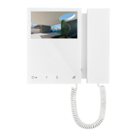
• Art. 6701W is a colour monitor equipped as standard with 4 buttons.
• Art. 6701W/BM is a colour monitor equipped as standard with 4 buttons and magnetic induction (Hearing loop) system. Not
supplied with backplate 6710.
• Art. 6701W/8 is a colour monitor equipped as standard with 8 buttons.
The monitor can be used in Simplebus2 audio/video systems.