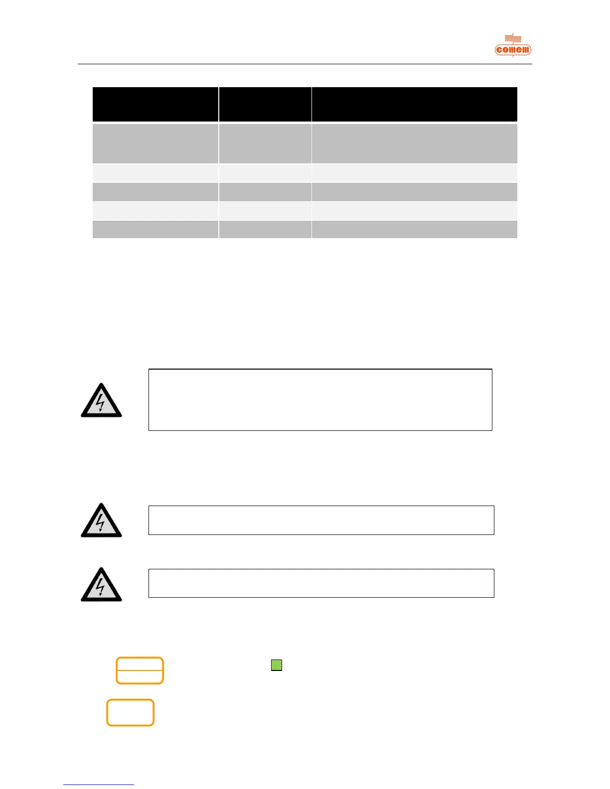
Instrument state S n 0
(channels 1, 2, 3 active with ventilation
excluded)
Alarm temperature A nnn 140
Release temperature t nnn 160
Ventilation Start value H nnn 100
Ventilation Stop value L nnn 90
3. INSTALLATION
The MB 103 Temperature Control Unit must be installed inside the switchboard compartment and then fixed in place with the fastening
components and screws provided.
Connect the power supply (universal power supply 24V – 220V AC/DC or 12V DC).
Connect the probes to the relative connection.
Connect the auxiliary circuits (alarm, trip, fault, fan) to the electrical connections.
4. CONNECTION
4.1 Power supply
4.2 Inputs
4.3 Relay tests
The operation test for all the relays can be performed via the menu.
Press the for about 2 seconds until the “TEST” LED comes on.
Press again to test the other relays.
Press to quit the relay test menu (see table below).
The instrument reads up to PT 100 probes.
Dust, humidity and corrosive gases should be avoided. Keep away from heat
sources. The maximum operating temperature of the instrument is 60 °C.