5
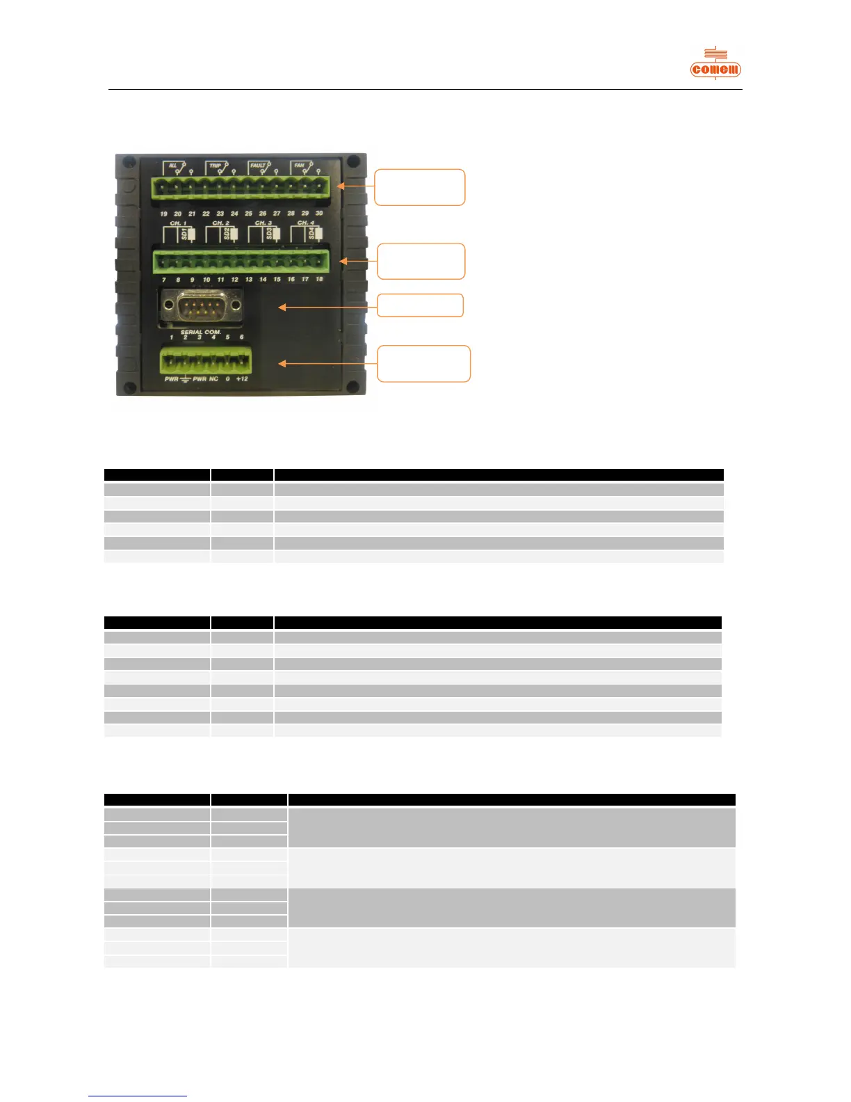
2.2.2 Rear panel
Fig. 3
Power supply
Terminal number Input Description of operation
1 PWR From 24 to 220V AC to DC universal power supply with +/- 10% variations allowed
2 Earth Must be connected using cable at least 1.5 mm in section
3 PWR From 24 to 220V AC to DC universal power supply with +/- 10% variations allowed
4 Terminal not connected
5 0 Input for 12V DC power supply
6 +12 Input for 12V DC power supply
Probe inputs (PT100)
Terminal number Input Description of operation
7 - 8 SD1PF Probe 1 cold pole input
9 SD1PC Probe 1 hot pole input
10 - 11 SD2PF Probe 2 cold pole input
12 SD2PC Probe 2 hot pole input
13 - 14 SD3PF Probe 3 cold pole input
15 SD3PC Probe 3 hot pole input
16 - 17 SD4PF Probe 4 cold pole input
18 SD4PC Probe 4 hot pole input
Auxiliary circuits
Terminal number Input Description of operation
19 ALL1 - C
Terminals of ALARM circuit
20 ALL1 - NC
21 ALL1 - NA
22 ALL2 - C
Terminals of RELEASE circuit
23 ALL2 - NC
24 ALL2 - NA
25 FAULT - C
Terminals of FAULT circuit
26 FAULT - NC
27 FAULT - NA
28 FAN - C
Terminals of VENTILATION circuit
29 FAN - NC
30 FAN - NA