COMESTERO GROUP M21/03.02
Rev.02
of 25/09/03
Page 17 of 34
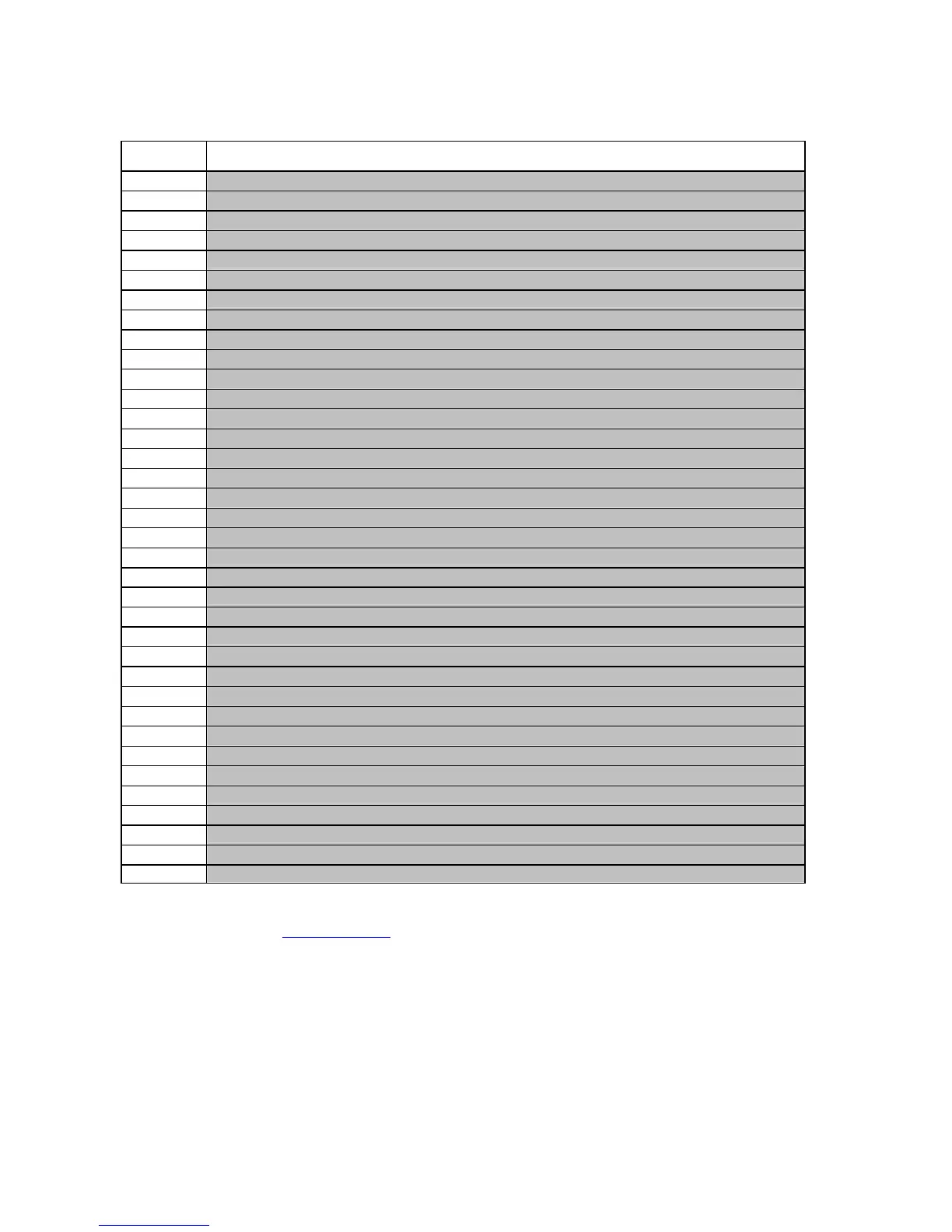
CONTROLS IMPLEMENTED ON RM5
Control Function
254 Simple poll
253 Address poll
252 Address clash
251 Address change
250 Address random
249 Request polling priority
248 Request status
246 Request manufacturer id
245 Request equipment category id
244 Request product code
243 Request database version
242 Request serial number
241 Request software version
240 Test solenoids
238 Test output lines
237 Read input lines
236 Read opto states
233 Latches output lines
232 Perform self check
231 Modify inhibit status
230 Request inhibit status
229 Request Buffered credit or error codes
227 Request master inhibit status
210 Modify sorter path
209 Request sorter path
197 Calculate rom checksum
196 Request creation date
195 Request last modification date
192 Request build code
184 Request coin id
170 Request base year
169 Request address mode
4 Request comms revision
3 Clear comms status variables
2 Request comms status variables
1 Reset Device
For the detailed description of each control listed above please refer to the CCTALK manual
available on this site: www.cctalk.org
All RM5 coin validators produced by implementing CCTalk protocol are configured as
VALIDATORS 00 (please refer to chapter 8.1. VALIDATOR CONFIGURATION). Each of them, in
order to meet the requirement of non modifiable condition, is programmed so that nobody can
intervene on the settings carried out by Comestero either through the usual
management/programming systems (Clone 5 and RM5 Programmer) or by acting on the output
connector.The protocol also identifies the type of physical interface to be used and defines the
voltage levels and suggests the appropriate circuits.
It suggests the type of connection (connectors). In particular for the coin validator, a 4 Pin and a 10
Pin connectors are suggested (and therefore used by our company) represented in para. 3.5.