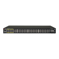
FIGURE 2 RJ-45 Cable and Cable Gland Assembly
1. Cable gland base
2. Clamping ring
3.
Rubber grommet
4. Gland dome
2. Use a wide at-blade screwdriver to remove the required (PoE OUT or
PoE IN) blanking cap from the T750SE.
3. Connect the cable to the Ethernet port in the AP.
4. Tighten the cable gland base to 7 N.m (62 in-lbs).
5. Wrap the clamping ring assembly around the rubber grommet. Make
sure that the clamping ring assembly fully encloses the rubber
grommet.
6. Seat the clamping ring assembly and rubber grommet in the cable
gland base.
7. Hand-ghten the gland dome.
Connecng the SFP Opc Module Using a Single
Diameter Cable
You can use a single diameter cable to connect to the SFP opc module.
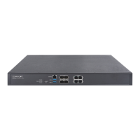
FIGURE 3 SFP module cable gland assembly
1. SFP transceiver
2. Cable gland gasket
3. Cable gland extender
4. Cable gland gasket
5. Clamping ring
6. Cable gland grommet / zipcord
cable gland grommet
7. Gland dome
8. Fibre cable
WARNING! The ber cable is extremely fragile and must be handled
with care.
NOTE: Do not insert the cable gland base/grommet/dome into the
extender unl the extender has been ghtened. Step 5 must be
performed before Step 6, else the ber cable will twist.
1. Place the cable gland base to the cable gland extender and ghten
the cable gland base to 7 N.m (62 in-lbs).
2. Fix the Cable gland extender gasket to the cable gland extender.
3. Feed the ber cable through the gland dome, cable gland grommet,
clamping ring, cable gland base, cable gland extender, and cable gland
gasket as shown in Figure 3.
4. Connect the ber cable to the SFP transceiver in the AP.
5. Tighten the cable gland extender to 7 N.m (62 in-lbs).
6. Insert the cable gland grommet into the clamping ring with the ber
cable in the center.
7. Insert the clamping ring into the cable gland base.
8. Tighten the cable gland dome to 7 in-lbs.
The SFP module is hot-swappable and can be removed with ngers or
simple tools.
Connecng the SFP Opc Module Using a Zipcord
Cable
You can use a zipcord cable to connect to the SFP opc module.
WARNING! The zipcord ber cable is extremely fragile and must be
handled with care.
NOTE: Do not insert the cable gland base/grommet/dome into the
extender unl the extender has been ghtened. Step 5 must be
performed before Step 6, else the ber cable will twist.
1. Place the cable gland base to the cable gland extender and ghten
the cable gland base to 7 N.m (62 in-lbs).
2. Fix the Cable gland extender gasket to the cable gland extender.
3. Feed the zipcord ber cable through the gland dome, zipcord cable
gland grommet, clamping ring, cable gland base, cable gland
extender, and cable gland gasket as shown in Figure 3.
4. Connect the zipcord ber cable to the SFP transceiver in the AP.
5. Tighten the cable gland extender to 7 N.m (62 in-lbs).
6. Insert the zipcord cable gland grommet into the clamping ring with
the zipcord ber cable in the two holes.
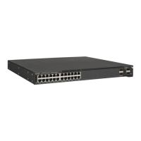
FIGURE 4 Zipcord grommet with cable
7. Insert the clamping ring into the cable gland base.
8.
Tigh
ten the cable gland dome to 7 in-lbs.
The SFP module is hot-swappable and can be removed with ngers or
simple tools.
Aaching the U-Joint Bracket to the Mounng Bracket
1. Posion the U-joint bracket on the mounng bracket.
NOTE: Moun
t the U-join
t bracket in any direcon on the mounng
bracket, preferably to allow AP azimuth adjustments. Then the AP
bracket allows AP elevaon adjustments.
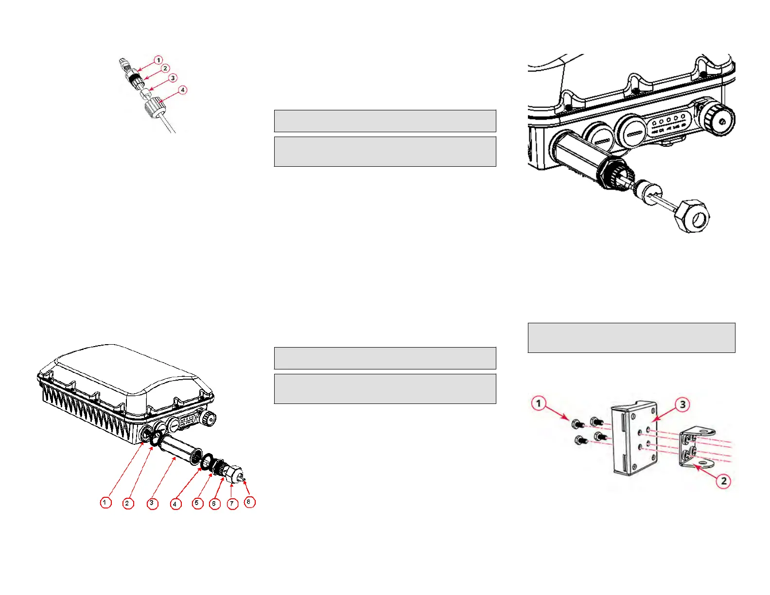
FIGURE 5 U-join
t br
acket aached horizontally to the mounng
bracket
1. Bolts
2. U-join
t bracket
3. Mounng bracket
2. Use four 1/4 - 28 bolt and washer sets (1) to mount the U-joint
bracket (2) to the mounng bracket (3). Tighten the bolts to 9.5 N.m
(84 in-lbs).
Copyright
©
2020 CommScope, Inc. All righ
ts reserved. Page 2 of 7
Published July 2020, Part Number 800-72283-001 Rev B