3. Connue with Aaching the Mounng Bracket to a Flat Surface on
page 3.
Aaching the Mounng Bracket to a Flat Surface
1. Place the mounng bracket at the locaon on the at surface where
you want to mount the AP. Use the holes on the mounng bracket as
a template to mark the locaons of the mounng holes.
FIGURE 6 Mounng bracket at surface holes
2. Remove the mounng brack
et from the at surface.
3. Drill holes required for the mounng hardware.
NOTE: The hardw
are required for mounng to a wall are not
included in the mounng kit.
4. Aach the mounng brack
et to the at surface using the mounng
hardware.
5. Using the mounng hardware instrucons, ghten the hardware to
secure the mounng bracket.
6. Connue with Aaching the Mounng Bracket to a Pole on page 3.
Aaching the Mounng Bracket to a Pole
1. Insert the open end of one steel clamp into the upper two slots on
the mounng bracket.
2. Take the other steel clamp and insert it into the lower two slots on
the mounng bracket.
NOTE: The clamps c
an be daisy-chained together to accommodate
larger poles.
3. Use the clamps to aach the mounng brack
et to the pole. Tighten
the clamps to 3 N.m (27 in-lbs) or per manufacturer’s specicaons.
FIGURE 7 Aaching the mounng brack
et to a vercal pole
4. Connue with Mounng the Linkag
e Bracket to the U-Joint Bracket on
page 3.
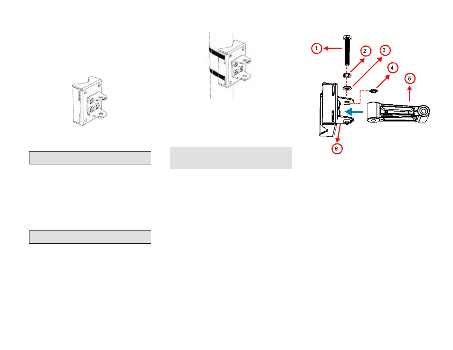
Mounng the Linkage Bracket to the U-Joint Bracket
1. The linkage bracket aaches to the U-joint bracket using an M8 bolt
and washer set. The linkage bracket is symmetrical, and either end
can be aached to the U-joint bracket.
NOTE: Make sure that linkage bracket is installed with its serrated
e
xternal-tooth lock washer on the inside of the U-joint bracket
anges. This ensures that the azimuth adjustment does not
change.
2. Loosely assemble the linkage bracket (1), the U-joint bracket (3), one
serra
ted external-tooth lock washer (2), and one M8 bolt and washer
set (4).
FIGURE 8 Aaching the linkag
e bracket to the U-joint bracket
1. M8 bolt
2. Lock w
asher
3. Flat washer
4. External-tooth lock
washer
5. Linkage bracket
6. U-joint bracket
3. Set the azimuth required by the AP.
4. Tighten the M8 bolt to 13.6 N.m (120 in-lbs).
5. Connue with Aaching the AP Bracket to the Linkage Bracket on
page 3.
Aaching the AP Bracket to the Linkage Bracket
Aach the AP bracket to the linkage bracket using the included bolt, lock
washer, at washer, serrated external-tooth washer and nut shown in the
illustraon below.
The linkage bracket is symmetrical, and either end can be aached to the
AP bracket.
Loosely assemble the AP bracket to the linkage bracket using the M8 bolt,
washer and nut set.
Copyright
©
2020 CommScope, Inc. All righ
ts reserved. Page 3 of 7
Published July 2020, Part Number 800-72283-001 Rev B