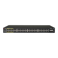
FIGURE 9 Aach the linkage bracket to the AP bracket
1. M8 bolt
2. Locker washer
3. Flat washer
4. External-tooth lock washer
5. Linkage bracket
6. AP bracket
7. Nut
NOTE: Make sure that the linkage bracket is installed with its serrated
external-tooth lock washer on the inside of the AP bracket anges. This
ensures that the elevaon adjustment does not change.
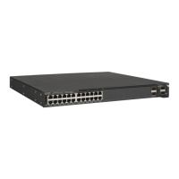
Aaching the AP Bracket to the Access Point
1. Place the AP bracket onto the back side of the AP so that the four
larger screw holes on the bracket align with the four screw holes on
the AP.
FIGURE 10 Aaching the AP bracket to the AP
1. AP
2. AP br
acket
3. Flat washer
4. Lock washer
5. Hex bolts
2. Use four 0.5-inch x 0.250-28 hex bolts with split lock and at washer
sets to mount the AP bracket to the AP. Tighten the bolts to 2.5-3.0
N.m (22-27 in-lbs).
CAUTION! Make sur
e that the screws are no longer than 0.5 inch.
If a screw is longer than 0.5 inch, it can damage the AP chassis.
NOTE: This kit may include e
xtra screws, nuts and washers. You
may use the extras where required.
3. Connue with Set the
Elevaon and Tighten the Elevaon Bolt on
page 4.
Set the Elevaon and Tighten the Elevaon Bolt
1. Set the elevaon required by the AP.
2. Tighten the M8 bolt to 13.6 N.m (120 in-lbs).
3. Connue with Powering the AP with AC on page 7.
External Antenna and Cabling Need to be Purchased
Separately
If the External Antenna opon is chosen over the internal sector antenna,
the External Antenna and Antenna Cable must be purchased separately.
NOTE: Beame
x is not available with external antennas.
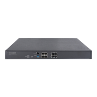
Mounng and Connecng 5 GHZ and 2.5 GHZ External
Antennas
NOTE: Mount the external antenna per manufacturer's instrucons.
1. Disconnect the AP from all power sources.
2. Unscrew the metal caps that protect the antenna connectors.
3. Connect external antennas to the N-type female antenna connectors
on the AP. Use a torque wrench to ghten the connectors to 1.58 N.m
(14 in-lb).
4. If the antennas come with RF coaxial cables (for example, a patch
antenna), physically mount the antennas at your desired locaon,
preferably on the same mounng structure as the AP.
FIGURE 11 T750SE Rear View
T750SE
Connecons
External Antenna Connecon
Vercal Horizontal
ANT0 X
ANT1 X
ANT2 X
ANT3 X
5. Apply weatherproong t
ape to the antenna connectors as described
in Connector Sealing Instrucons on page 5.
CAUTION! If you ar
e not connecng external antennas to the AP,
make sure that the metal caps remain installed and securely
fastened to protect the interfaces from elements, such as water
and dirt.
Copyright
©
2020 CommScope, Inc. All rights reserved. Page 4 of 7
Published July 2020, Part Number 800-72283-001 Rev B