Connector Sealing Instrucons
NOTE: N-Type connectors shown are representave examples.
NOTE: Applying sealing tape to both ends of the cable is recommended.
Step 1: Cleaning the Connectors and Your Hands
1. Clean all traces of dust, grease, and oil from your hands
2. Clean o any traces of dust, grease, and oil from the N-type bulkhead
connector external threads
3. Make sure that the connectors are dry before connuing.
Step 2: Connecng the Cable with the Connector
1. If the AP is powered on, disconnect the AP from the power source.
CAUTION! Make sure that you disconnect the AP from the power
source to avoid electrocuon or equipment damage.
FIGURE 12 Connecng the Cable with the Connector
2. Unscrew the metal cap that protects the antenna connector. Place the
met
al cap in a safe place, in case you need it later.
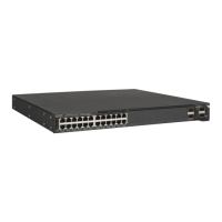
3. Connect the cable to the connector. Use a torque wrench to ghten
the cable coupling nut to 1.58 N.m (14 in-lb). If you do not have a
torque wrench or if you are ghtening a knurled coupling nut (as
shown), hand-ghten the cable coupling nut unl the internal gaskets
are compressed, but do not overghten.
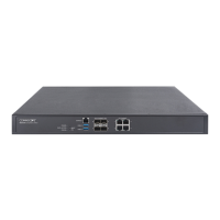
Step 3: Wrapping the Exposed Connector Threads
1. Depending on the width of the sealing tape, either fold the tape in
half or cut it to t the exposed connector threads
2. Stretch the tape per the manufacturer’s instrucons
3. Working clockwise, gently stretch the sealing tape as you install it so
that it covers the connector thread between the cable coupling nut
and the base of the connector.
Make sure that the nal wrap is approximately ush with the cable
coupling nut, and then cut the sealing tape.
FIGURE 13 Wr
apping the Exposed Connector Threads
NOTE: Cut, do not tear
, the sealing tape. If the sealing tape is
overstretched, it loses its self-amalgamang properes.
Step 4: Wrapping the Internal Layer of the Electrical
Tape
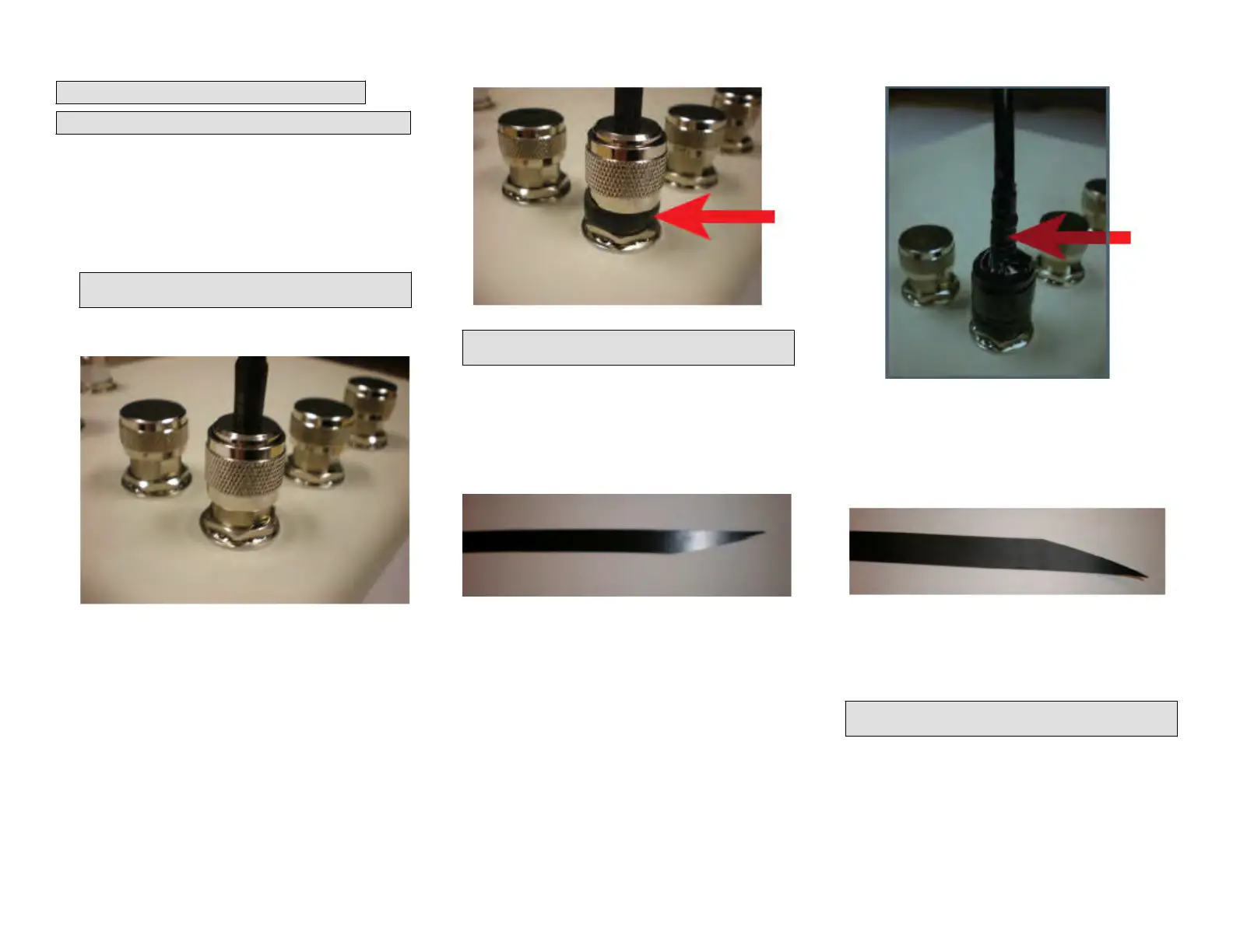
1.
Using scissors, cut the end of the electrical tape at an angle. This will
allow the electrical tape to be applied with minimal bulk.
FIGURE 14 Cung the End of the Electrical Tape
2. Wrap the electrical tape clockwise from the beginning of the cable
c
oupling nut t
o just past the heat shrink tube on the cable. Do not
cover the sealing tape installed in Step 3: Wrapping the Exposed
Connector Threads on page 5.
FIGURE 15 W
r
apping the Electrical Tape
Step 5: Wrapping the Main Sealing Tape
1. Using scissor
s, cut the end of the sealing tape at an angle. This will
allow the sealing tape to be applied with minimal bulk.
FIGURE 16 Cung the Sealing Tape at an Angle
2. Working clockwise, gently stretch the sealing tape from the beginning
of the sealing tape ins
talled in Step 3: Wrapping the Exposed
Connector Threads on page 5 and connue wrapping to 12 mm (0.5
in.) past the electrical tape installed in Step 4: Wrapping the Internal
Layer of the Electrical Tape on page 5.
NOTE: Cut, do not tear
, the sealing tape. If the sealing tape is
overstretched, it loses its self-amalgamang properes.
Copyright
©
2020 CommScope, Inc. All rights reserved. Page 5 of 7
Published July 2020, Part Number 800-72283-001 Rev B