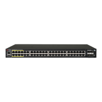
FIGURE 17 Wrapping the Sealing Tape
3. Gently knead the sealing tape from top to boom to make sure there
are no gaps and to amalgamate the sealing tape.
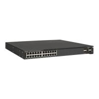
Step 6: Wrapping the Outer Layer of Electrical Tape
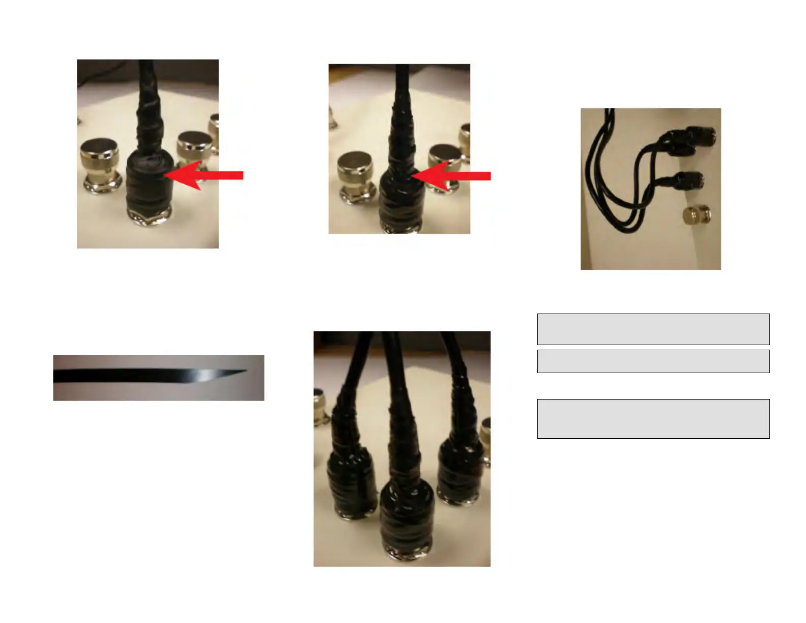
1. Using scissors, cut the end of the electrical tape at an angle. This will
allow the electrical tape to be applied with minimal bulk.
FIGURE 18 Cung the Electrical Tape at an Angle
2. Wrap the electrical tape clockwise to completely cover the sealing
tape and c
onnue wrapping to 12 mm (0.5 in.) past the sealing tape
installed in Step 5: Wrapping the Main Sealing Tape on page 5.
FIGURE 19 Wr
apping the Electrical Tape
Step 7: Repeang f
or the Other Cables
Repeat the connector sealing instrucons for the three antenna
connectors, as shown in Figure 18.
FIGURE 20 Repeang for Other Cables
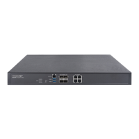
Step 8: Creang Cable Drip Loops
Physically mount the AP and antennas at your desired locaon, preferably
on the same mounng structure.
Form 80-mm to 130-mm (3-in. to 5-in.) drip loops with the cables.
FIGURE 21 Creang Cable Drip Loops
Earth Grounding the AP
CAUTION! Make sur
e that earth grounding is available and that it meets
local and naonal electrical codes. For addional lightning protecon,
use lightning rods and lightning arrestors.
NOTE: The color coding of ground wires varies by region. Before
c
ompleng this step, check your local wiring standards for guidance.
Using the factory-supplied ground wire and ground screw/washer set,
connect a g
ood earth ground to the AP chassis ground point.
CAUTION! The T750SE AP includes one 9 mm st
ainless steel M6 x1
earth ground screw with split lock and at washers. Make sure that any
replacement screw is no longer than 9 mm. If a screw is longer than 9
mm, it can damage the AP chassis.
Copyright
©
2020 CommScope, Inc. All rights reserved. Page 6 of 7
Published July 2020, Part Number 800-72283-001 Rev B