Installation Part 3: Installation and Starting Up
22
Part 3: Installation and Start ing Up
Installation
A
C
A
B
16
DBF
2
18
6
12
24
1
2
3
4
5
6
7
F
1
: :
1.
2.
3.
DBF
2
18
6
12
24
1
2
3
4
5
6
7
F
1
: :
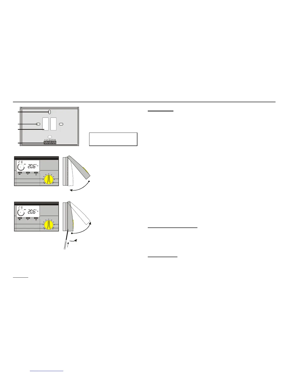
Installation
1. Secure the base to the wall (approx. at eye-level).
2. Connect terminals 1+2 on the base with the terminals on
the OT-BUS of the boiler. The BUS connector is designed
to prevent reversed poling. The connections can be
swapped over.
3. Connect the remote telephone switch [Terminals 3+4],
if required.
4. Connect the outdoor sensor [Terminals 5+6],
if required.
5. Snap on the top part of the controller,
position and hook in at the center of the top edge, use a
little pressure to pivot it down onto the base and press on.
Dimensions: 147 mm x 97 mm x 33 mm
A: Retention holes (for assembly on switch socket)
B: Cutout for cable entry
C: Connection terminals (PIN 1 is on the left)
Connection terminals
PIN 1+2 OT-BUS
PIN 3+4 remote telephone switch
PIN 5+6 outdoor sensor
Disassembly
Insert a screwdriver in the opening on the underside and
lever off. Take hold of the underside and pivot up.
PIN 1+2 OT-BUS