29
K09657H02 | PROC-CAL/002/03 USER MANUAL | V. 11/07/2023
. MAINTENANCE
Fig. 10 Fig. 11
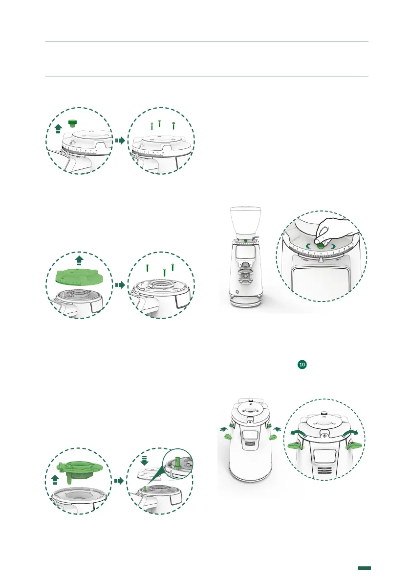
12.3.8. Remove the regulator by pulling
upwards (Fig. 11). Loosen the upper burs
support screws with a #3 Hex Allen key,
according to (Fig. 12).
Fig. 11 Fig. 12
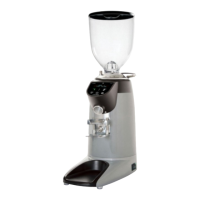
12.3.9. Remove the upper holder by pulling
upwards to access the grinding cavity,
clean the interior with the help of a brush
or vacuum cleaner and remove any coee
residue from the grinding cavity (Fig. 13).
When reassembling, proceed by reversing
the disassemble steps and to align the
regulator hole to the regulator brake post
according to (Fig. 14).
Fig. 13 Fig. 14
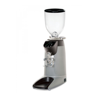
Only for grinders with a Lock Load
System
12.3.10. To avoid losing the position of the
regulator scale with respect to the current
grinding point, it is essential to tighten the
setting of the grinding regulator using the
adjusting brake by turning it clockwise (Fig.
15).
Fig. 15
12.3.11. To access the grinding cavity, insert
the tools into the hexagonal holes located on
the Lock Load System ( ) according to (Fig.
16). Turn both tools in the direction shown by
the icons or according to (Fig. 17).
Fig. 16 Fig. 17