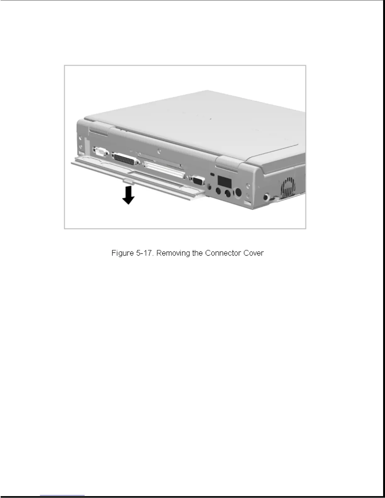
Reverse this procedure to install a connector cover.
5.4.4 Auxiliary Battery Compartment Door
See Section 5.3.4 for instructions on how to remove and replace the
auxiliary battery compartment door.
5.4.5 Memory Expansion Board
The memory expansion board is installed from the outside of the computer
and is located behind the connector cover on the rear of the computer. The
assembly consists of two memory boards and a carrier, which are
preassembled and installed as a unit. To remove and replace a memory
expansion board, complete the following steps:
1. Turn off the computer and unplug the power cord.
2. Open the connector cover and loosen the two screws [1]
(Figure 5-18). The screws are captured in the memory expansion board
carrier and do not separate from the carrier.




 To Next Page