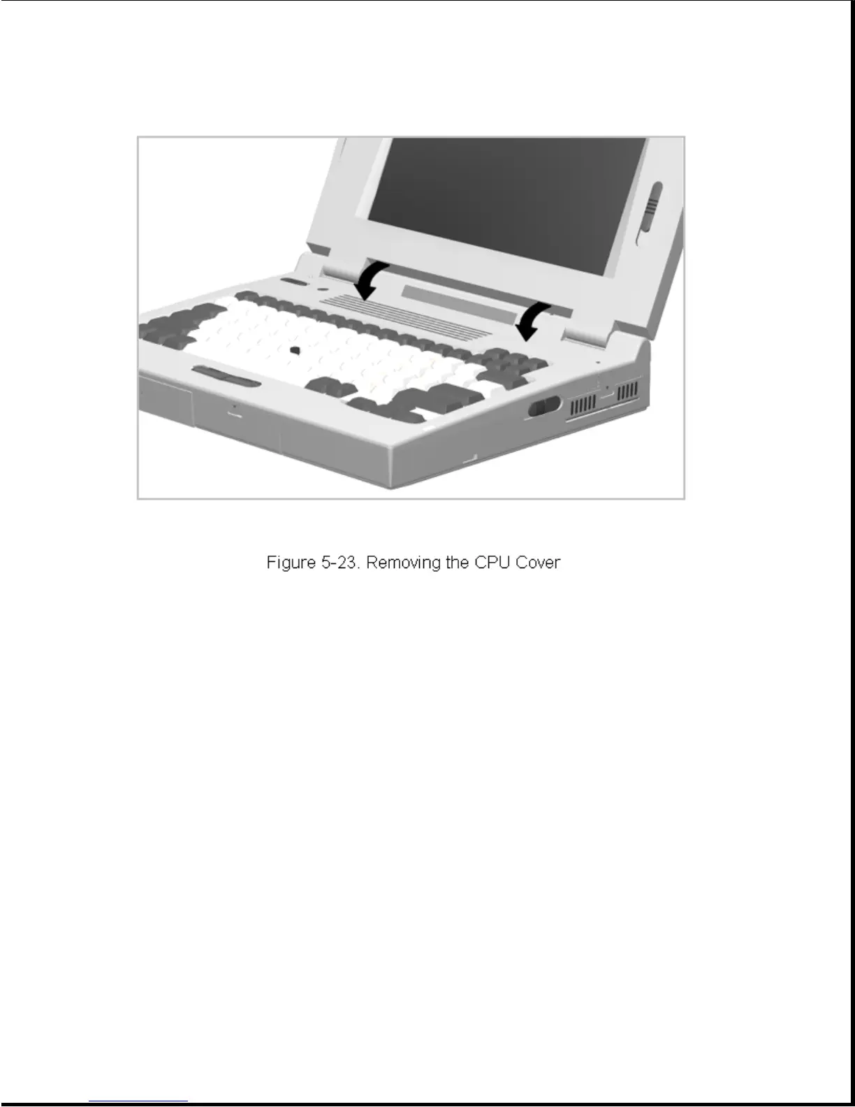
4. Tilt the CPU cover forward and out of the computer (Figure 5-23).
Reverse the above procedure to install the CPU cover assembly.
IMPORTANT: A set of warning labels is included with each CPU cover
assembly spare parts kit. Select a label with the language that
matches the keyboard language and install the label in the
upper right corner of the cover. This label contains a warning
message to prevent physical discomfort and harm. Installation
of this label is essential.
5.5.2 Power Switch Actuator
To remove the power switch actuator, complete the following steps:
1. Remove the CPU cover as described in Section 5.5.1.
2. From the bottom side of the CPU cover, squeeze the tabs and push the
switch actuator and its installed spring out of the cover
(Figure 5-24).