MNC-0300-036 11 of 26 Revision E
Unpacking and Installation
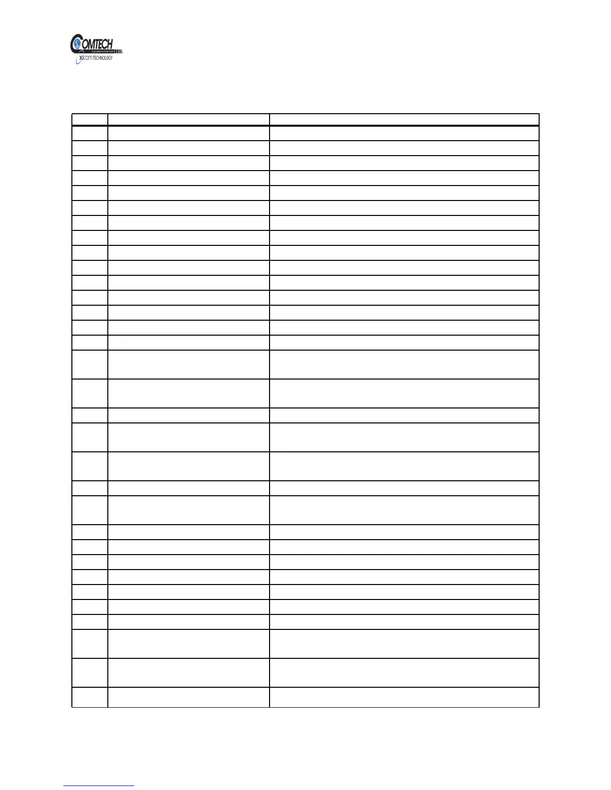
Table 1, Digital Monitor and Control Connector J1 Pinouts
Pin Signal Description
A Reserved Reserved
B RS-232 RX
C RS-232 TX
D Reserved Reserved
E RS-232 GND
F Reserved Reserved
G Reserved Reserved
H Reserved Reserved
J Reserved Reserved
K System GND System GND
L RS-422/485 Transmit +
M RS-422/485 Transmit -
N RS-422/485 Receive +
P RS-422/485 Receive -
R RS-422/485 GND
S Summary Fault A -- Normally
Open Contact
S Closed to U when Fault
T Summary Fault A -- Normally
Closed Contact
T Opened to U when Fault
U Summary Fault A Summary Fault A Common
V Summary Fault B -- Normally
Open Contact
V Closed to X when Fault
W Summary Fault B -- Normally
Closed Contact
W Opened to X when Fault
X Summary Fault B X Summary Fault B Common
Y RF Inhibit Opto isolator Low RF Inhibit -- Connect Pin Y to either Pin Z or Pin a,
and Pin g to Pin f to Inhibit RF
Z System GND System GND
a System GND System GND
b +24 VDC Out +24 VDC Current limit of 100 mA
c +24 VDC Out +24 VDC Current limit of 100 mA
d A/B Amplifier A/B Amplifier select
e Re-program Computer Re-program Computer command Low
f +15 VDC Out +15 VDC Monitor and Opto-isolator Bias Supply
g RF Inhibit Opto isolator Hi RF Inhibit -- Connect Pin g to Pin f, and Pin Y to either
Pin Z or Pin a to Inhibit RF
h External Interlock Opto isolator
Low
Connect Pin h to either Pin Z or Pin a for normal
operation.
j RF Output Analog
V
o
= 10
(PdBm - 47.27)/19.05
EAR EXPORT CONTROLLED: The information contained in this Manual refers or relates to a product that is subject
to the U.S. Export Administration Regulations (EAR). Transfer of data herein by any means to a Foreign Person,
whether in the U.S. or abroad, may require an export license from the U.S. Department of Commerce.