MNC-0300-036 10 of 26 Revision E
Unpacking and Installation
Monitor and Control Connector
To externally control the amplifier a M&C interface is provided. The
connector is a 32-pin MIL style waterproof connector.
The Monitor and Control connector provides these interfaces for the use
of the customer:
• COM1 — RS-232 Serial Port.
• COM2 — RS-422/ RS-485 Serial Port.
• Two sets of Form “C” Relay contacts for Summary Fault indication.
• External Interlock
• RF Inhibit Control
• 24 VDC @ 100 mA maximum
• 15 VDC for monitoring purposes only.
• Hardware Address Select.
Monitor and Control Pinouts
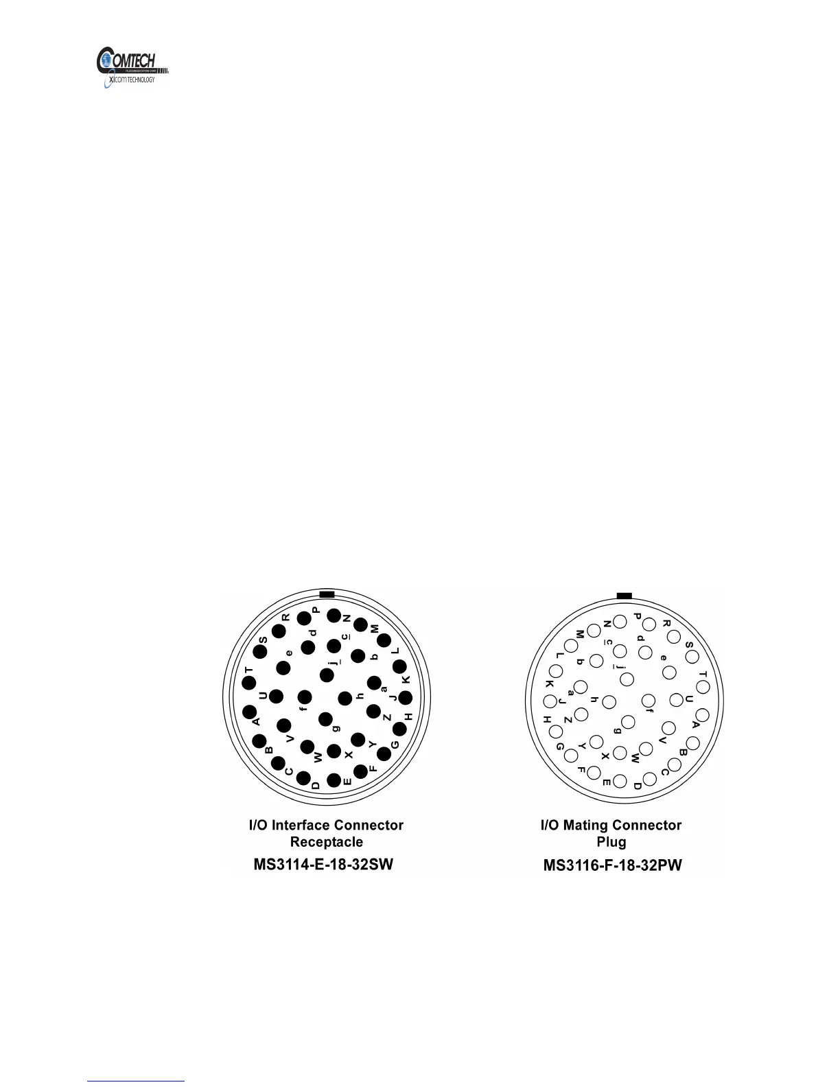
Figure 4 , Digital M&C Connector Pin Layout shows the pin layout and
Table 1 , Digital Monitor and Control Connector J1 Pinouts lists the pinouts
for the typical Digital Monitor and Control Connector on the Antenna
Mount Power Amplifier.
Figure 4, Digital M&C Connector Pin Layout
EAR EXPORT CONTROLLED: The information contained in this Manual refers or relates to a product that is subject
to the U.S. Export Administration Regulations (EAR). Transfer of data herein by any means to a Foreign Person,
whether in the U.S. or abroad, may require an export license from the U.S. Department of Commerce.