Connecting Serial Devices 14
Connecting Serial Devices
This section contains the following topics:
• Connecting your serial devices
• Building cables
• Serial connector pinouts
• Building loopback connectors to test ports
Note: Go to Building the Serial Ribbon Cable
on Page 33 for connector
information for the RTS 1-Port Embedded adapter.
Connecting Devices
Use this procedure to connect asynchronous serial devices to the RTS ports.
Make sure that you have configured the ports using the NS-Link driver
or SocketServer for the correct communications mode before
connecting any devices. The default mode in the NS-Link drivers is RS-
232. There is a remote possibility that connecting a peripheral for the
wrong mode could damage the peripheral.
1. Connect your serial devices to the appropriate port on the DeviceMaster RTS
using the appropriate cable. You can build your own cables using the Building
Cables for Serial Devices discussion (Page 14).
Note: Refer to the hardware manufacturer’s installation documentation if you
need help with connector pinouts or cabling for the peripheral device.
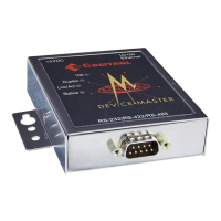
2. Verify that the devices are communicating properly:
• The amber Rx LEDs shows that the port is
connected to another RS-232 device or
receiving data in RS-422/485 mode.
• The green Tx LED shows that the data is
transmitting.
Note: The port LED activity on the RTS 16/32RM
may be inconsistent until the port has been
opened. After a port is opened the LED
activity works as documented.
Building Cables for Serial Devices
You can build your own null-modem or straight-through serial cables using:
• Building Null-Modem Cables (RS-232)
on Page 15
• Building Straight-Through Cables (RS-232/485)
on Page 15
• DB9 Connector Pinouts
on Page 16
• Building Additional DB9 Loopback Plugs
on Page 16
• RJ45 Connector Pinouts
on Page 16
• Building Additional RJ45 Loopback Plugs
on Page 17
• B
uilding an RS-485 Test Cable on Page 17
Caution
TX1
*
RX1*
DB9 LEDs
RJ45 LEDs
Rx
Tx
Rx
Tx
* Represents port number.