Appendix A. RTS 1-Port Embedded System Installation 36
Connecting the Power and Verifying Installation
Connecting the Power and Verifying Installation
Use the following procedure to supply power to the RTS and verify the hardware
installation.
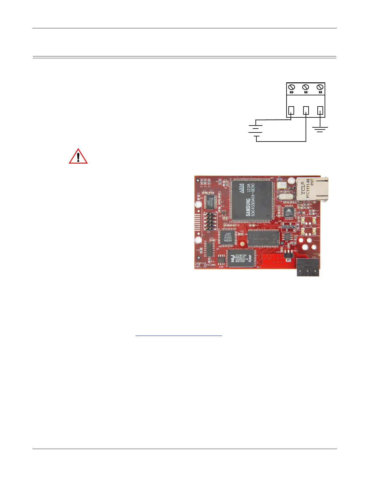
1. Wire the supplied screw terminal
connector to a 5VDC local power source
as shown below.
Note: Observe proper ESD techniques
when connecting and
disconnecting the RTS.
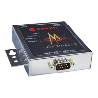
2. Plug the screw terminal connector into JP1 by aligning the scalloped edge.
3. Apply power to the RTS.
4. Verify that the network connection for the RTS is functioning properly.
The LEDs are located
between the RJ45
connector and the power
terminal block.
• An amber Status LED
(D1) on the RTS
should be lit,
indicating you have
power and it has
completed the boot
sequence.
Note: The Status
LED flashes
while booting
and it takes
approximately
15 seconds for
the boot sequence to complete.
•The red Link Active LED (D2) should be lit, indicating that you have a
working Ethernet connection.
•If the Duplex (D3) LED is lit, it indicates full duplex activity.
• If the red 100 (D4) LED is lit, it indicates a working 100 MB Ethernet
connection (100 MB network, only).
5. Go to Configuring the Network Setup
on Page 12 for default network settings
and how to configure the RTS for use.
Earth Gnd
Return
Positive
Wire gauge:
AWG 12-22
5VDC
+
-
Caution
LED