Hardware Installation 8
RTS 16-Port Installation - External Power Supply
RTS 16-Port Installation - External Power Supply
Use the following procedure to install the RTS 16 with an external power supply.
1. Record the MAC address, model number, and serial number of the
DeviceMaster RTS unit on the customer service label provided.
You may need the MAC address during driver configuration. The serial
number and MAC address are located on a label on the device. The MAC
address starts with 00 CO 4E.
2. Place the RTS on a stable surface, or optionally mount the RTS in a rack.
Rack Installation:
a. Attach the L brackets to the interface using the screws supplied with the
unit.
b. You can mount the unit facing in either direction.
c. Attach the L bracket into your rack.
Follow these guidelines when mounting the RTS in a rack.
• If the RTS is installed in a closed or multi-rack assembly, the
operating temperature of the rack environment may be greater
than the ambient temperature. Be sure to install the RTS in an
environment that is compatible with the maximum rated ambient
temperature (Environmental Specifications
on Page 21).
• Make sure that the mechanical loading is level to avoid a
hazardous condition; such as, loading heavy equipment in the rack
unevenly. The rack should safely support the combined weight of
all equipment in the rack.
• Slots and openings in the cabinet are provided for ventilation. To
ensure reliable operation of the RTS and to protect it from
overheating, maintain a minimum of 1 inch of clearance on all
sides of the unit.
• AC power inputs are intended to be used with a three-wire
grounding type plug, which has a grounding pin. Equipment
grounding ensures safe operation. Do not defeat the grounding
means and verify that the RTS is reliably grounded when mounting
within the rack.
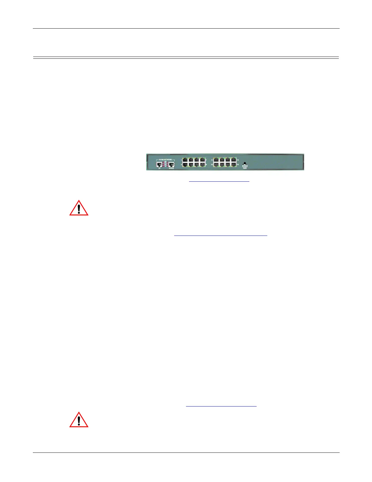
3. Connect the RTS to the same Ethernet network segment as the host PC using
one of the following methods.
• Ethernet hub or switch (10/100Base-T): Connect to the port labeled UP
on the RTS using a standard Ethernet cable.
• Server NIC (10/100Base-T): Connect to the port labeled DOWN on the
RTS using a standard Ethernet cable.
• Daisy-chaining RTS units: Connect the port labeled DOWN on the first
RTS to the port labeled UP on the second RTS or other device using a
standard Ethernet cable.
Note: Do not connect multiple units until you have changed the default IP
address, see Default Network Settings
on Page 12.
If you plan on using the NS-Link device driver, make sure that you do
not connect RS-422/485 devices until the appropriate port interface
type has been configured in the driver. The NS-Link default port
setting is RS-232.
Larger picture, Page 24
Caution
Caution