Appendix A. RTS 1-Port Embedded System Installation 34
Mounting the RTS
Mounting the RTS
Use the following procedure to mount the RTS 1-Port Embedded.
1. Carefully remove the RTS from the anti-static bag, following standard
electrostatic device handling procedures.
Note: Write down the MAC address located on a label on the bottom (solder
side) center of the RTS because you may need it during configuration.
2. Mount the RTS as appropriate for your environment using 1/4” stand-offs to
separate the RTS from the base.
Note: The maximum diameter of the metal stand-offs should be 0.175” with a
4-40 machine screw.
• Chassis ground connection through the power cable: stand-offs can
be metal or plastic.
• No Chassis ground connection through power supply: stand-offs
must be metal.
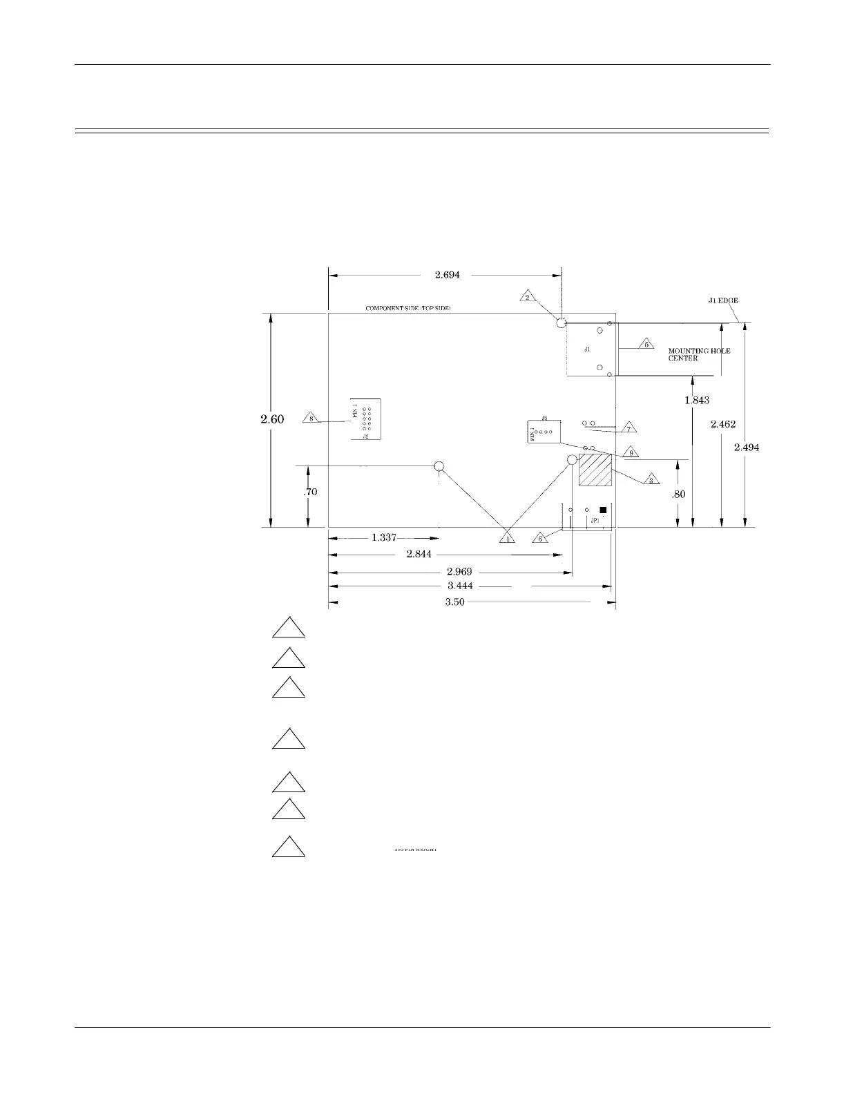
1 Non-plated/non-grounded mounting holes 0.116” diameter (+/-0.003”).
2
Plated/chassis grounded mounting hole 0.116” diameter (+/-0.003”).
3
WARNING: Holes in hatched area are not mounting holes.
4 Maximum component height above board is 0.55”.
5
Ethernet connection J1: J1 overhangs board edge by 0.14” and the
the height is 0.55”.
7
LED light pipe mounting holes.
8
Serial port connector J2: 0.1” pin spacing, 0.025” square pin diameter,
and 0.230” pin height.
9
Debug port connector J3: 0.1” pin spacing, 0.025” square pin diameter,
and 0.230” pin height.