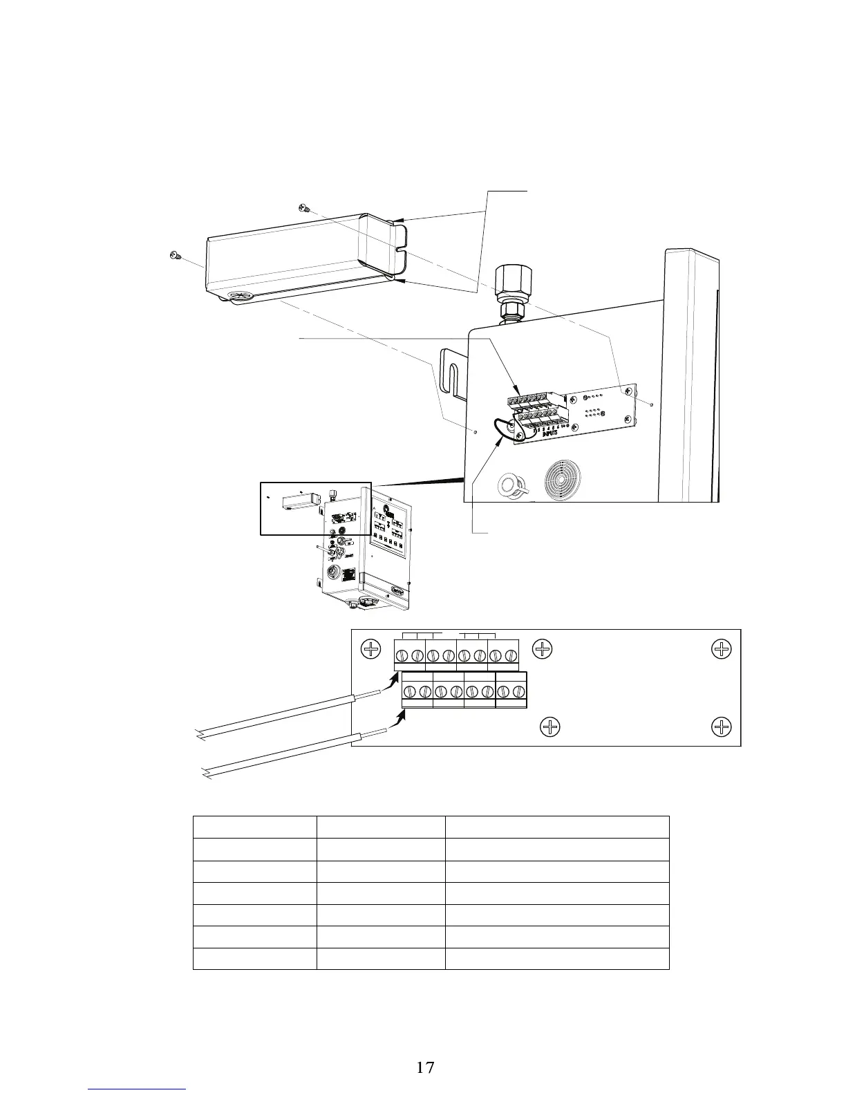
CONNECTING AN OXYGEN DEFICIENCY MONITOR
The CryoWiz™ is equipped with a terminal strip under a metal cover on the left side of the enclosure to which the
normally closed dry contact signal from an oxygen deficiency monitor can be connected. Remove the cover and
connect the wires from the oxygen deficiency monitor to terminal 1 of the CryoWiz™ accessories circuit board as
shown below and in Table 1.
Terminal Number
Terminal Number Description
1 V+ Oxygen Sensor
2 V+ Dry Nitrogen Pressure Switch
3 V+ Reserved
4 V+ Reserved
5 V+ Reserved
6 V+ Reserved
Table 1
2-Conductor Cable From
Internal Pressure Switch
to Input #2
INPUT TERMINALS:
8 upper + 8 lower connections.
Input #1 upper and lower is for the
optional oxygen deficiency monitor
connection. Input #2 upper and
lower is used by the internal
pressure switch. Remaining inputs
are unused.
GASKET TOP & BOTTOM:
Do Not Remove!!!
Required to prevent
moisture collection
on circuit board.
v
+
J3
INPUTS
V
+
G
G
4
5
6
3
2
1
+12V to +24V to “C”
Relay Contact on O
2
Monitor
Wires from
Oxygen
Deficiency
Monitor
“N.O.” Relay Contact
on O
2
Monitor