SETTING REMOTE ALARM OUTPUTS
The CryoWiz™ is designed to interface with an external alarm system. Relay contacts are brought out through
the 8-pin circular connector on the left side of the cabinet. The pin connections on this connector are set to
connect directly to a CONCOA alarm (see section “Connecting a Remote Alarm”). CONCOA alarms are designed
such that the contacts are Normally Closed (N.C.). In an alarm condition, these contacts will open. This is the
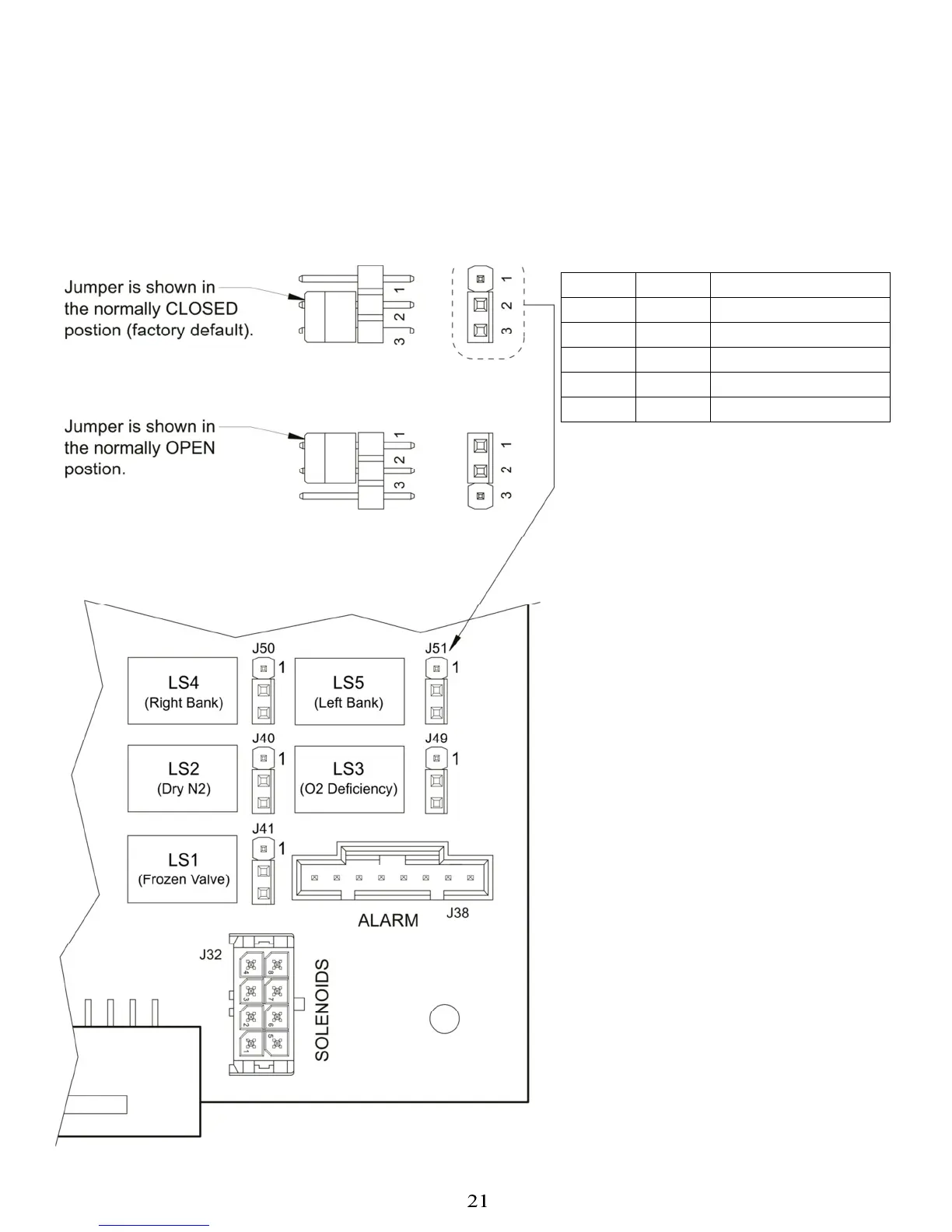
factory default. It is possible to change these contacts to Normal Open (N.O.). The figure below shows the
location of the jumpers on the lower right side of the main circuit board. There are five jumpers; one for each
alarm relay as shown in Table 4. To change a contact from N.C. to N.O., follow the steps below and see table 4:
Relay JUMPER
FUNCTION
LS1 J41
Frozen Valve Alarm
LS2 J40
Dry N2 Pressure Low
LS3 J49
Oxygen Deficiency
LS4 J50
Right Bank Depleted
LS5 J51
Left Bank Depleted
1. Turn OFF AC power to the system.
2. Open front door by loosening the 4
screws on the front cover.
3. Locate the jumpers on the circuit
board.
4. Change the jumpers to cover the
center and the bottom pins of each
relay.
5. Close door and re-secure it to the
cabinet.
6. Make the necessary connections to
the alarm, and plug the alarm cable
into the alarm connector on the
side of the cabinet.
7. Turn AC power ON.