8
UMC 600IS Installation Manual
2.6 Load Cell Wiring
All units are equipped with a six-wire load cell
connector. Condec supplies load cell cable in various
lengths (see Table 2-3 on page 5). One end of the
cable attaches to the indicator; the other end has
stripped and tinned wires for connection to a junction
box. The UMC 600IS is supplied with a blank six-pin
connector that can be attached to existing load cell
cables by the installer.
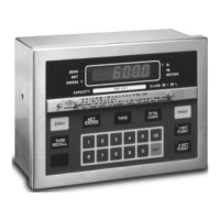
Figure 2-5 shows the load cell output connector and
the location of J1 on the back of the indicator.
Table 2-6 shows the load cell connector pin
assignments.
Figure 2-5. J1 Load Cell Connector-facing
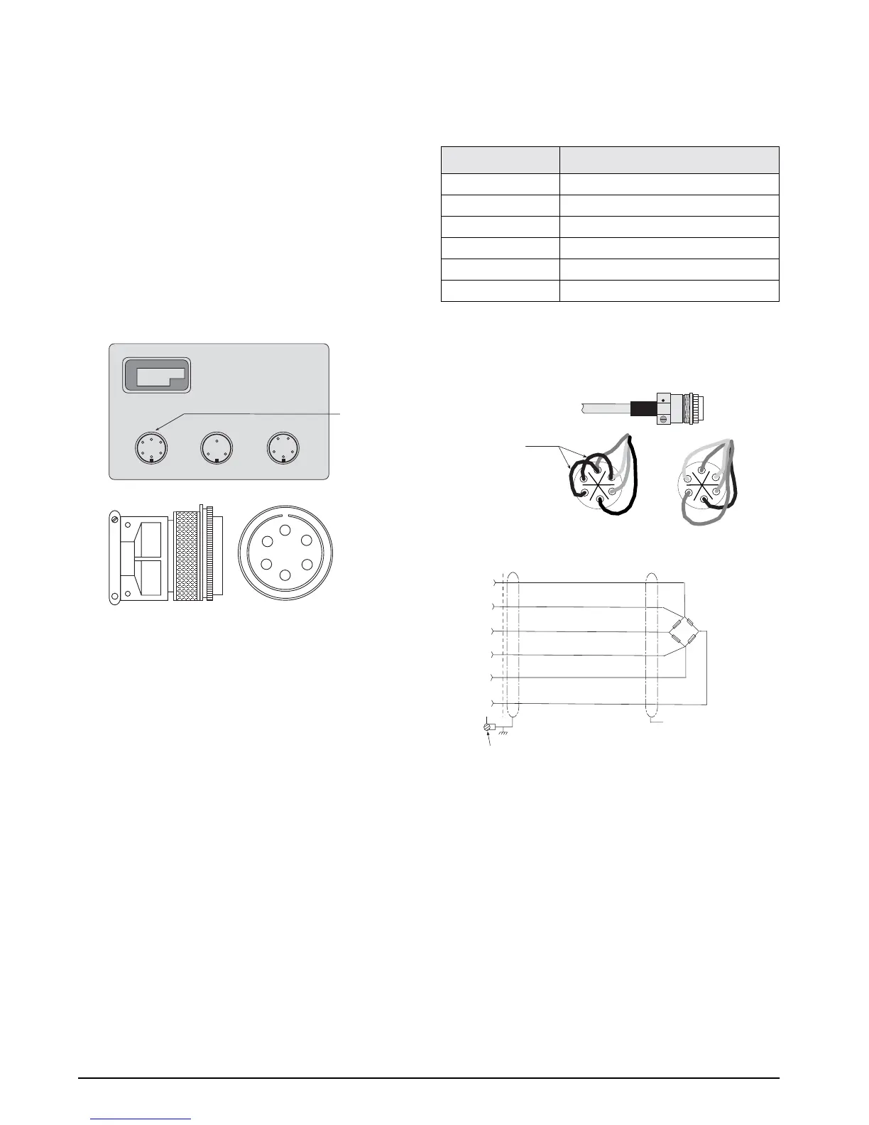
For four-wire load cell connections, short the sense
lines to the excitation lines as shown in Figure 2-6.
Figure 2-6. Load Cell Wiring
J1
J2 J3
J1
Load Cell
Connector
A
B
C
D
E
F
Pin
Function
A +EXCITATION
B –EXCITATION
C +SIGNAL
D –SIGNAL
E +SENSE
F –SENSE
Table 2-6. Load Cell Connector Pin Assignments
E
A
C
B
F
D
+SEN
+EXC
+SIG
–EXC
–SEN
–SIG
P1
Check load cell color
code for proper wiring
No connection
Connector shell or chassis ground
A
B
C
D
E
F
Six-Pin Female
P1
Jumper wires
A (+EXC) to E (+SEN)
B (–EXC) to F (–SEN)
4-Wire Configuration 6-Wire Configuration
A
B
C
D
E
F