10 UMC 600IS Installation Manual
2.8 Troubleshooting and Testing the 600IS
Troubleshooting the system components in a safe area can be done in the normal manner utilizing any test
equipment that is necessary. However, prior to any test or measurement that is done in a hazardous area, the plant
manager or safety official must be notified to obtain permission or specific instructions.
The following basic procedures should be observed to provide a safe installation.
•Follow all plant safety procedures.
•Verify what type test equipment is allowed in the hazardous area.
•Do not bring into the hazardous area any inductive continuity testers.
•Do not bring any capacative discharge type devices into the hazardous area.
•Ask the plant authority if the use of non-sparking tools are required.
2.8.1 Troubleshooting
The following should be a guide during the installation of the weighing system in a hazardous location.
•Troubleshooting should only be done by qualified field service scale installation personnel.
•Component level repair is not permitted on Factory Mutual approved equipment.
•A factory trained technician can replace plug-in IS barrier equipment in the safe area.
• It is manditory to return the UMC 600IS to the factory for repair and full testing.
•Tampering with the intrinsically safe equipment voids the Factory Mutual approval.
• Safe area voltage measurements are as follows:
The power supply output voltage can be measured at
the following terminals:
•TB2-4 +VDC (positive lead)
•TB2-5 DC Com (negative lead)
Shorting these terminals will blow the
fuse in the intrinsically safe barrier
module 59267.
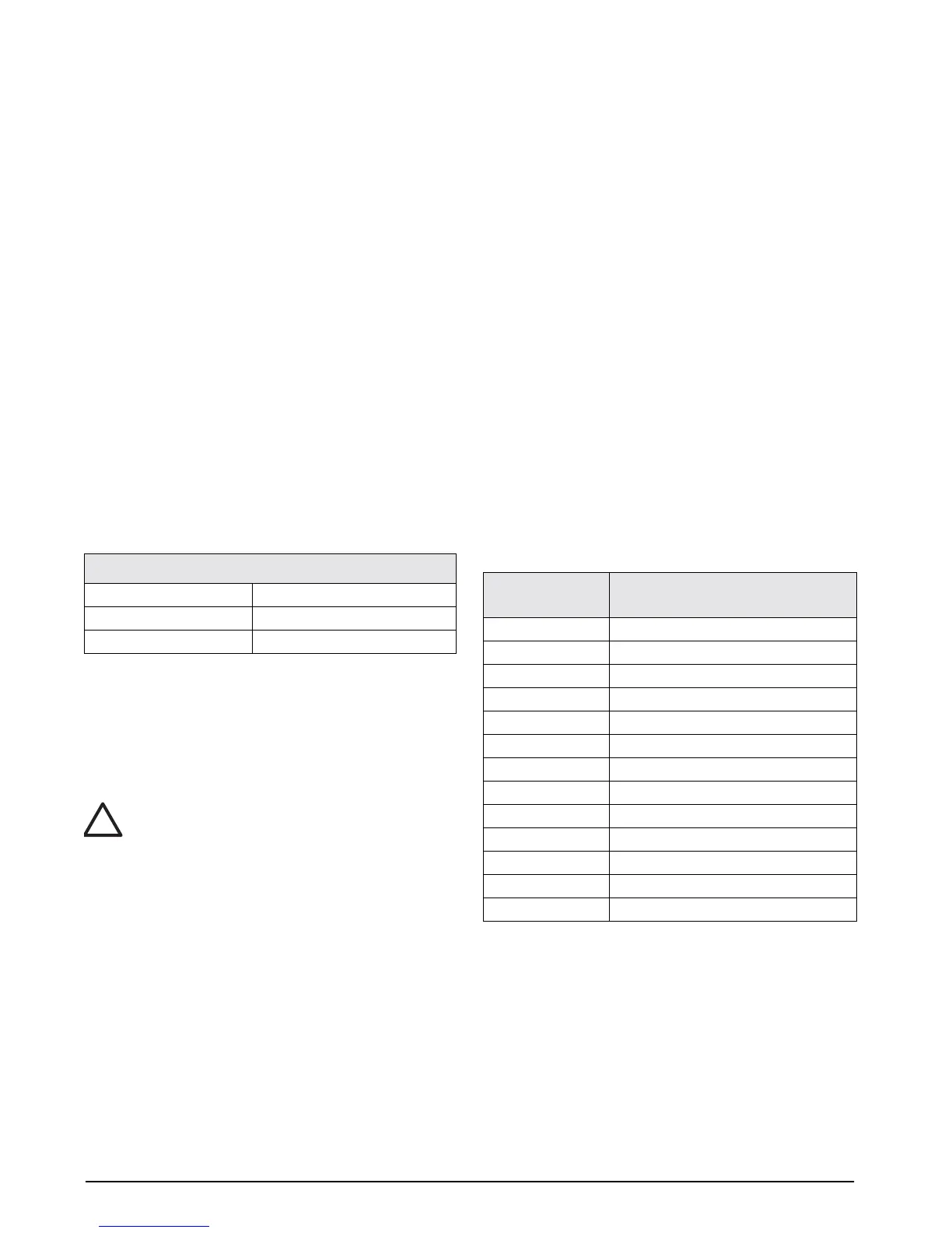
Field replaceable parts are listed below for the UMC
600IS digital weight indicator.
Power Supply Output Voltage
No load 8.0 +/- 0.2 VDC
One load cell 7.6+/- 0.2 VDC
Four load cells 6.5 +/- 0.2 VDC
Table 2-8. Output Voltage
!
Caution
Condec Part
Number
Description
58805 Power supply
65004 Power supply board assembly
59267 Plug-in barrier
59942 Fuse, 0.25A
55683 I/O barrier
57415 I/O barrier board assembly
54966 Plug-in I/O barrier
56214 Battery pack module
54087 Battery charger
52216 Tilt stand (battery unit)
54074 Load cell connector (6 pin)
54080 Power connector (3 pin)
54084 I/O connector (5 pin)
Table 2-9. Field Replaceable Parts