Installation and Wiring
5
2.2 Cable Requirements
Intrinsically safe cables used in the hazardous area are specified on the Control Drawings 54136, Sheets 2 and 3.
Since all cables have internal inductance and capacitance, only the cables listed are safe to use with this
intrinsically safe system. Table 2-2 provides specifications for maximum cable length based on group
classification. A list of Factory Mutual approved cables is shown in Table 2-3.
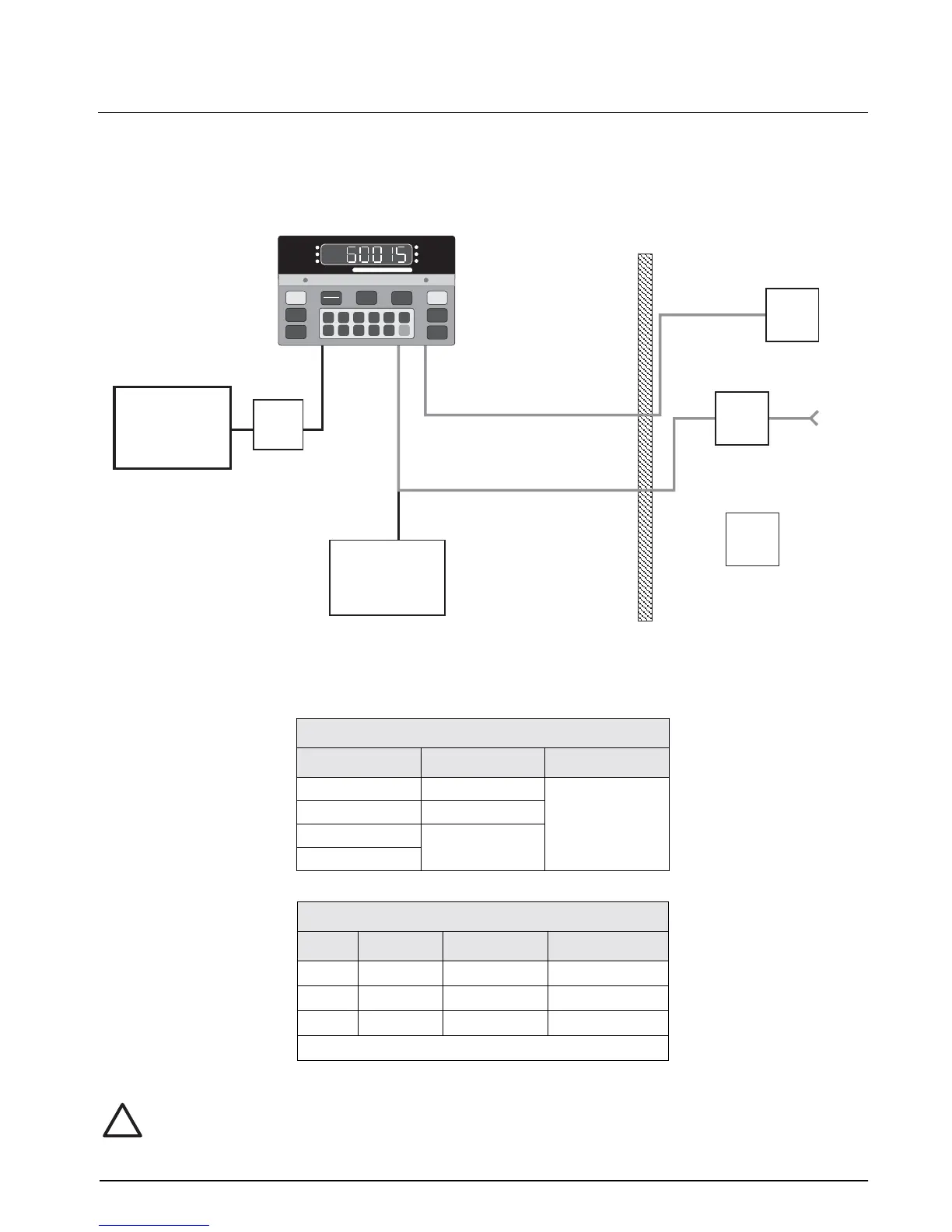
Figure 2-1. Intrinsically Safe System Diagram
Note:
Either power supply or battery can be used, but not both simultaneously.
Use only Factory Mutual approved cables.
Maximum Cable Length,
Group Cable 1 Cables 2 & 3
A, B 75' 800'
C 300'
D 500'
E, F, G
Table 2-2. Maximum Cable Lengths
Factory Mutual Approved Cable
Cable Type Condec PN Belden P/N
1 Power
45897 (
x
)
8618
2 Serial I/O
45898 (
x
)
9942
3 Load Cell
45898 (
x
)
9942
(
x
) = feet in increments of 50
Table 2-3. FM Approved Cable Lengths
Safe AreaHazardous Area
Divisions I and 2
Class I, Groups A, B, C, D
Class II, Groups E, F, G
Class III
FM-Approved
load cells
(Up to 4)
Battery Power
Supply Models
Only
Junction
Box
Cable 3
Load Cell
Cable 2
Serial I/O
Power
Supply
Cable 1
Power
115 VAC
I/O
Isolation
Barrier
Battery
Charger
1
6
2
7
3
8
4
9
5
0
CE
ENT
TARE
RECALL
ZERO
NET
GROSS
TARE
lb/kg
CONV
PRINT
1 SET
POINT
2 SET
POINT
CAPACITY
600 x 0.1
ZERO
NET
GROSS
lb
kg
MOTION
!
Caution