20 UMC 600IS Installation Manual
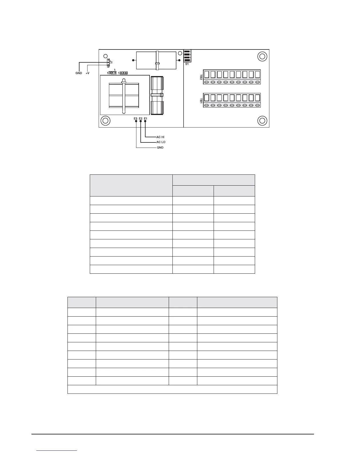
Figure 3-8. Analog Module Setup and Wiring
Table 3-11. Baud Rate and Switch SW1 Settings
Table 3-12. Description of Terminal Boards TB1 and TB2
1 23456789
1
2
3
456
7
89
S
S2
Baud rate
SW1 Setting
1 2
1200 Off Off
2400 On Off
4800 Off On
9600 On On
Mode 3 4
Normal operation Off Off
0 VDC/4 mA (test only) On Off
10 VDC/20 mA (test only) Off On
0–10 VDC/4–20 mA ramp (test only) On On
TB1 Description TB2 Description
1 4–20 mA 1 Zero
2Ground 2 Gross/Net
3 0–10 VDC output 3 Tare
4 Alarm 4 Start
55Ground (–20 mA input) common
6 +20 mA TXD 6 RS-232 TXD
7 –20 mA TXD 7 +5 VDC
8 +20 mA RXD 8 –20 mA
9 -20 mA RXD 9 Demand print
NOTE: Jumper TB1-8 to TB2-7 (5 VDC) to make the analog output module an active device.