6-5
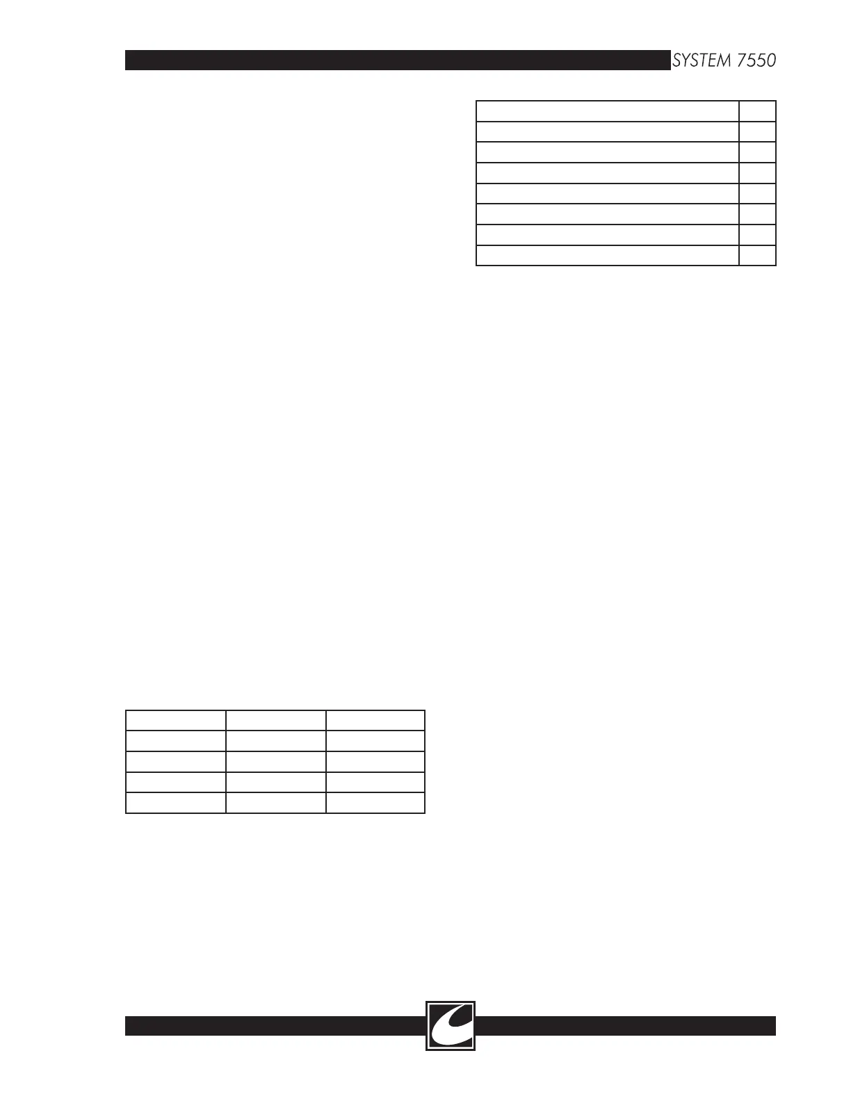
VCON = 9V when HVDC is 200V (0V-9V)
PCON = 8.8V at full dial cut (0V - 8.8V)
ILIM = 3.8V at full dial cut (0V - 3.8V)
VGAS = 6.2V at 10 SLPM (.15v to 6.2V)
6.2.14 Keyboard Scanner [U5]
The 74C922 allows a 4X4 matrix keyboard to
be connected. When a Front Panel switch is
pressed, the location of the switch is latched into
the device and the signal KB_DA (keyboard data
available) is
SET. Only one switch press is stored
and gets cleared after the device is read.
6.2.15 5V Monitoring [U29]
U29 is a microcontroller supervisory device that
automatically sets the “RST” when the 5V sup
-
ply is less than 4.5V. A short interruption of the
mains power will cause a system reset to occur.
On the input of U29 (pin 1) is a comparator
(U35) that will cause a reset to occur if the 5V
exceeds 5.7V. The pin “RST” is active high and
“/RST” is active low.
6.2.16 Output PIA [U21]
Dedicated output PIA for the control
microcontroller to latch control logic to system
functions. This device has three (3) output ports
and each will be described briefly.
PORT A: CON_D0 - CON_D7
Dedicated for mode identification to the Power
Control Assembly. When a mode activation
occurs, the controller latches a Hex count into this
register and the magnitude of the count identi
-
fies to the RF Logic FPGA which mode is being
requested.
Cut: 39h Blend 1: 37h Blend 2: 35h
Blend 3: 33h Blend 4: 31h Blend 5: 29h
Blend 6: 27h Blend 7: 25h Blend 8: 23h
Blend 9: 21h Bipolar: 6Fh PPT: 43h
Spray: 82h ABC™: C3h
PORT B: OUTPUT RELAY SELECT
These outputs connect to a relay driver (U23)
on this PCB Assembly. Upon an activation, hex
counts are latched into this register for relay clo
-
sure dependent on mode and method of RF acti
-
vation.
Handcontrol 1 - Cut or PPT. Coag 31h
Handcontrol 1 - Spray Coag
51h
Handcontrol 2 - Cut or PPT. Coag
32h
Handcontrol 2 - Spray Coag
52h
Argon Beam Coagulation
08h
Bipolar A0h
Footcontrol - Cut or PPT. Coag
34h
Footcontrol - Spray
54h
PORT C: CIRCUIT ENABLES
The following signals are
SET during activation as
shown:
PSRQT: Power Supply Request
Enables the high voltage power supply circuit -
Enabled for all mode activations.
PC_EN: Power Control Enable
Enables the Power Control Circuit to inter
-
face with the HV Control Circuit for Power
Control when Cut, Blend, Bipolar or Pinpoint
modes are activated.
LVT_EN: Low Voltage Triac Enable
Enables the low voltage triac (125V) when Cut,
Blend or Bipolar are activated.
HVT_EN: High Voltage Triac Enable
Enables the high voltage triac (185V) when
Pinpoint, Spray, or ABC™ are activated.
AR_EN: Argon Enable
Enables the flow control circuit when ABC™ is
activated.
6.2.17 T_MON [U35]
The monitor microcontroller verifies that for every
activation of RF Output, a tone is generated.
T_MON is a signal with the same frequency as
the tone generated.
6.3 Power Control Assembly [A4]
This assembly controls output power of all modes
and has the driver logic for both RF Amplifiers.
It is important to remember that this system has
two separate RF Amplifiers and each amplifier
operates in a different manner. The amplifier
against the back wall is called Full Bridge (FB)
and is used for Cut, Pinpoint, Blend, and Bipolar
Modes. The other amplifier is against the side
wall and is only activated for Spray and ABC™
modes. This discussion will focus on each ampli
-
fier independently.