6-13
To enable the correct triac, the signals HVT_EN
(Pinpoint, Spray & ABC) or LVT_EN (Cut,
Blend, & Bipolar) must be high. These signals
originate on the Display Board Assembly.
Referring to the schematic (Figure C-4a), a
signal labeled LK_CON can also reduce the
HVDC. V
CON is the HVDC requested volt-
age, however P
ERR (power error) can override
VCON and reduce the HVDC to a lower volt-
age if measured power is greater than requested
power in Cut, Blend, Bipolar and Pinpoint modes
only. LK_CON can also reduce HVDC if the RF
Leakage exceeds calibrated limits (see calibration
section). RF Leakage is typically not a problem
in any mode except Spray, and then only when no
load is on the output. Should the RF Leakage
exceed calibrated limits of 140mA (200 ohm
load), then this signal is positive with respect to
ground which causes a reduction in the HVDC.
When Spray mode has a load, then leakage is not
an issue and the HVDC returns to the V
CON set
point. To sum up, P
ERR can override and reduce
voltage in Cut, Blend, Bipolar and Pinpoint only.
LK_CON can reduce HVDC in all modes except
ABC™.
Transistor Q1 has a label HVR (High Voltage
Reset) attached, and is enabled following each
activation. HVR switches on a transistor of the
HVPS that pulls the voltage down to idle in a
time of about 100mS.
The last section of this circuit to be covered is
the HV Monitoring. Note on the schematic the
inputs labeled HV_MON, followed by a preci
-
sion rectifier. This circuit is an exact duplicate of
the HV_SNS signal previously discussed on both
this assembly, and also on the HV power supply
assembly. A ratio of the HVDC is sampled at
HV_MON; filtered and rectified for a DC voltage
on the cathodes of the output diodes. The resis
-
tors R9 & R6 divide the monitored voltage down
by one-half so that it will not exceed 5V. U1B is
a non-inverting amplifier that is calibrated for 1V
when the HVDC is at 50V. The resolution of this
signal is 20mV/V, or for each 20mV measured on
U1-7, the HVDC is 1V.
6.6 Argon Flow Control [A1]
See Figure C-4b for this section. The argon gas
flow control circuitry provides control functions
to produce a regulated argon gas mass flow rate
at the ABC™ handpiece tip. The requested mass
flow rate (V
GAS) signal originates on the unit
front panel, and is user controlled by the ABC™
power setting in the Automatic mode, or by the
user specified flow rates in the Manual and Endo
Modes. V
GAS has a range of 0.7V to 6.2V.
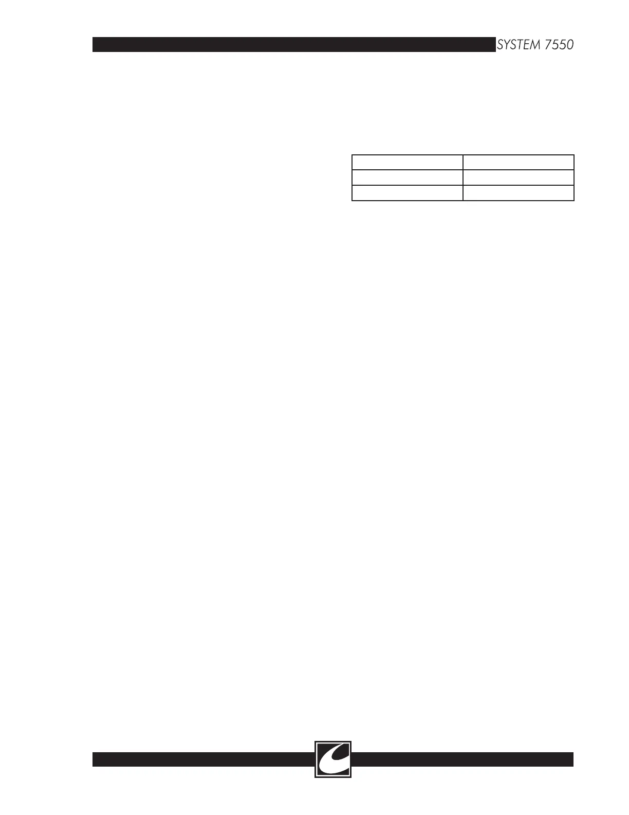
Argon Modes and Flow Rate Ranges (liters per
minute):
Automatic Mode 1.0 - 10 lpm
Manual Mode 0.5 - 10 lpm
Endo Mode 0.1 - 4.0 lpm
The Mass flow regulator is a closed loop system.
The requested mass flow rate is compared with
the requested flow rate and the result is an error
signal that adjusts a servo controller to either
increase or decrease the argon flow. To under
-
stand the circuit, we will first identify the pneu
-
matics which the circuit operates.
6.6.1 Pneumatic Circuit
See Figure 6.3 for this section. Tank pressure indi
-
cated on the pressure gauge, located on the rear
of the cart, is indicative of the quantity of remain
-
ing argon gas. A low pressure pneumatic/electric
switch connected to the high pressure tank line
closes if the tank pressure falls below approxi
-
mately 240 psi. Closure of this switch is used to
warn the user of minimal remaining gas supply
in the tank, indicated on the unit front panel by
illuminating the yellow “low tank” indicator in the
ABC™ section.
The high pressure of the argon tanks is reduced
to approximately 30 psi by a pneumatic regula
-
tor. If for any reason, pressure downstream of the
pneumatic regulator should exceed 50 psi, a safety
relief valve opens to minimize the risk of excessive
pressure in the low pressure lines. Continuing
downstream of the pneumatic circuit, a solenoid
valve opens during ABC™ activation periods.
This valve acts as a safety valve where it can be
closed to shut argon flow off, if necessary. The
proportioning valve is the controller for argon
flow (solenoid and proportioning valve are on a
common manifold) that increases and decreases
gas flow as a result of the control signal developed
by the control electronics.
Immediately following the pneumatic manifold is
a dampener to reduce any oscillations of the gas
flow that may occur. The next element in the low
pressure pneumatic circuit is the sensing orifice,
recognizable by the five (5) ports for argon tubing
connections. The sensing orifice is a calibrated