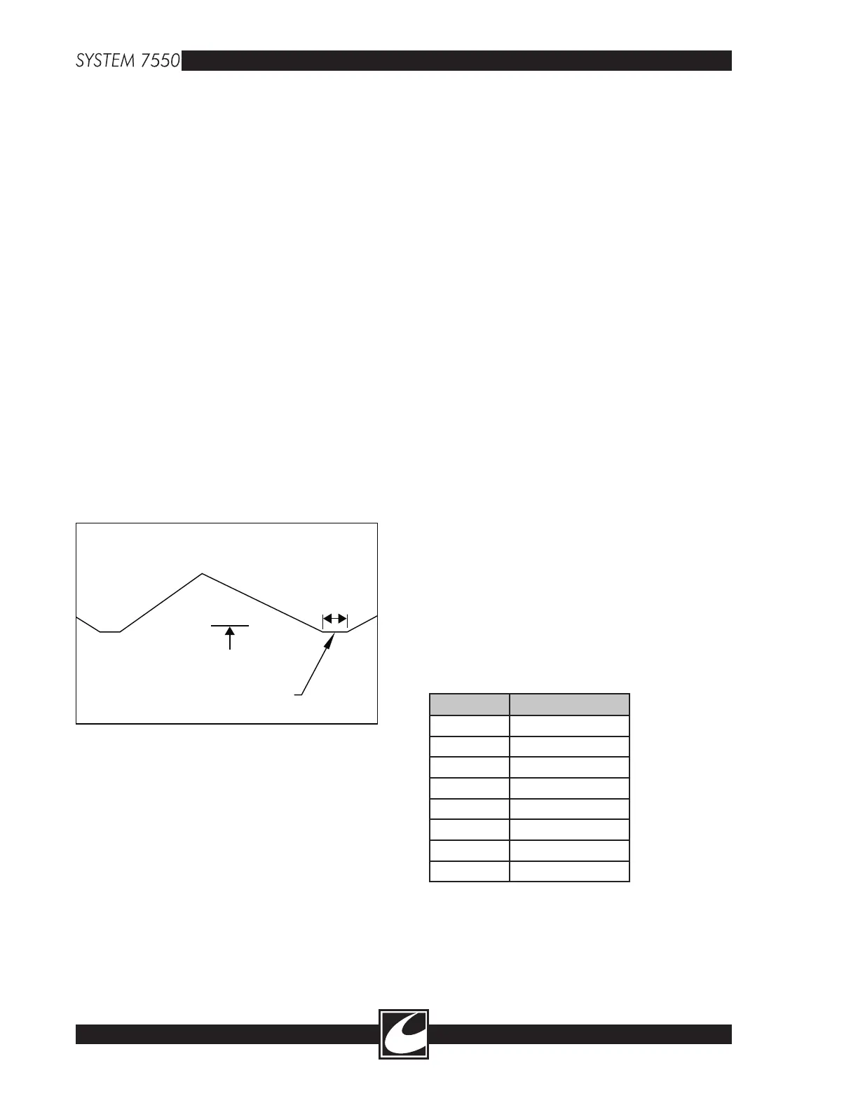
5V/DIV
1mS/DIV
U14,14
GND
400uS
"FLAT SPOT"
Figure 3.1 RAMP Flat Spot
8-2
• Connect a DVM from TP2 (CAL-10) to TP3
(2VARM).
• Adjust R2 (ARMCAL-10) for 0V ±.01V.
8.4.2 150 Ohm A.R.M. Calibration
• Place 150 ohms across the two leads of a dis
-
persive electrode cable.
• Connect a DVM from TP1 (CAL-150) to TP3
(2VARM).
• Adjust R1 (ARMCAL-150) for 0V ±.01V.
8.5 High Voltage Calibration (HV/
Flow Control Assembly - A1)
8.5.1 HV RAMP Calibration
• Connect an oscilloscope probe to TP 6
(RAMP).
• Connect the oscilloscope ground to TP2
(Gnd).
• Set the oscilloscope for 5V/Div and 1mS/Div.
Trigger the oscilloscope for the bottom of the
RAMP signal at the “flat spot” of the RAMP.
(See Figure 8.1)
• Activate ABC without a load connected to the
output.
• Adjust RA4 (HV ADJ) for 200V±2V
HVDC.
8.5.3 HV_MON Adjust
• Connect a voltmeter to +DC and -DC
(HVDC) on A7.
• Set Pure Cut power to 50W.
• Activate Pure Cut and adjust the power setting
of Pure Cut to get 50V at HVDC.
• Connect the voltmeter to TP1 (HVMON) on
the HV/FLOW Control (A1) assembly.
• Adjust RA1 (HVMON) for 1V ±30mV at
TP1 with 50V ±.6V at HVDC.
8.6 Argon Flow Calibration (HV/Flow
Control Assembly - A1)
8.6.1 dP Calibration (Differential Pressure)
• Connect a DVM to TP3 (dP) and TP2 (Gnd).
• With the System 7550™ in idle mode, adjust
RA2 (dP ADJ) for 0V.
8.6.2 PABS Calibration (Absolute Pressure)
• Connect a DVM to TP4 (PABS) and TP2
(Gnd)
• With the System 7550™ in idle mode, adjust
RA5 (PABS ADJ) as listed in the table below
for the altitude where the system is placed
into service or proportional to the difference
between two listed altitudes.
ELEVATION TABLE
Altitude Pabs Calibration
Sea level 5.22V
1000 ft.
5.01V
2000 ft.
4.81V
3000 ft.
4.60V
4000 ft.
4.39V
5000 ft.
4.19V
6000 ft.
3.98V
7000 ft.
3.78V
8.6.3 Flow Rate Calibration (Optional)
• Connect an ABC accessory to the System
7550™.
• With the System 7550™ in idle mode, adjust
RA7 (RAMP) to set the flat spot at 400uS.
8.5.2 High Voltage Adjust
CAUTION: RF burns can occur when skin
comes in contact with exposed RF leads.
Ensure RF leads are properly connected to an
analyzer or placed safely away from incidental
contact.
• Connect a volt meter to the +DC and -DC
(HVDC) terminals of the High Voltage
Power Supply (A7). Set the scale for 200V.
• Set ABC power for 20W to 50W.