Figure 6.2 Line Sync/RAM
6-11
6.4.4 HVPS Low Voltage Components
The NPN transistor, Q6, provides the supply
voltage for the low voltage components on this
assembly. The voltage source for Q6 is the AC
LO, where R26 limits the current and the zener
diode (12V) sets the voltage on the cathode of
D6 at about 10V. This 10V is used to provide
the supply voltage to U3 & U2 of this assembly.
The monitoring circuit will test for this 10V, and
should a failure occur where this voltage is too
high or too low, the system activation will be ter
-
minated.
The sense transformers are driven at about 40
KHz by U3 & U2 with the outputs Q and /Q
out of phase by 180°. The sense transformers are
set up for a center tapped push-pull drive signal.
When the top transistors (Q1 & Q5) are ON,
they pull current from the center tap to ground
which produces a signal on the secondary. The
top transistors then switch OFF and the lower
transistors (Q4 & Q2) switch ON, reversing the
current through the primary and reversing the
polarity on the output.
6.5 HV/Flow Control Assembly [A1]
The HV/FLOW Control assembly provides two
unrelated unit functions. High Voltage Power
Supply (HVPS) control and Argon Flow manage
-
ment circuits are both on this assembly. The sche
-
matics (Figures C-4a and C-4b) for this assembly
are on two pages with the high voltage control
schematic and the argon flow control schematic
on separate sheets for clarity.
in a specific DC voltage at light loads (R
L>1K
ohms), and then the DC voltage will be reduced
for heavier loads (R
L<1K ohms) for power regu-
lation. The HVPS & HV Control circuit make
up a control loop, and a control circuit loop by
nature feeds on itself such that one action in the
loop results in another action, which results in
another action, etc.
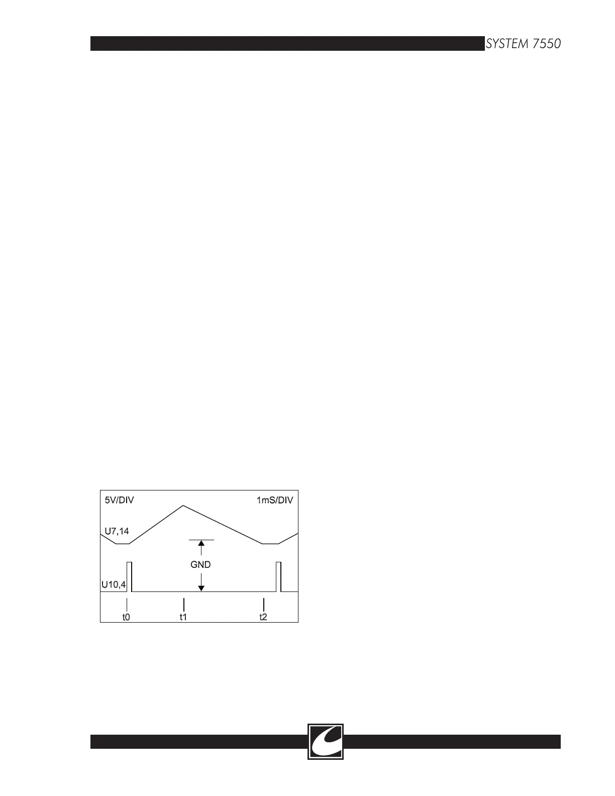
6.5.1 Line Synchronization Circuit
For this section, refer to Figure C-4a. The high
voltage power supply (HVPS) is phase controlled
and must be synchronized with the AC line volt
-
age. The synchronization is accomplished by the
zero crossing detector (U5-7) that is driven by
F_LN (J3-13), a replica of the AC Line Voltage
which comes from the low voltage line transform
-
er secondary. The sine wave of F_LN is converted
to a square wave at U5-7 and this results in a
50µS pulse at U10-4.
The lower trace of Figure 6.2 shows the 50µS
trigger pulse that is synchronized with zero cross
-
ing. The upper trace represents a ramping wave
-
form that is ultimately used to initiate the HVPS
triac trigger. The generation of the “cyclic ramp”
waveform is accomplished with a circuit loop.
The components of the loop will be covered in the
next few paragraphs.
To provide a simple description of this circuit, we
will start at the voltage divider with the switch, S1
(RA7, R66, R67, & R68). The switch (S1) is set
for either 50Hz or 60Hz operation. To the right
of S1 is a precision clamp (U7B & U7C) with
diodes on the outputs. The outputs of the preci
-
sion clamps, if viewed with an oscilloscope, are a
square wave with a rate of “Line Frequency x 2”
or 120Hz when the line frequency is 60 Hz.
A precision clamp will control the anode of the
output diode to the lowest voltage on the two
inputs. With 0V on the inverting (-) input, the
anode of the output diode will be 0V and when
the inverting input switches high (5V), then the
anodes of the output diodes have the same voltage
as S1-C (3V @ 60 Hz or 2.5V @ 50 Hz).
Following the precision clamp is a differential
amplifier (U7A) with a gain of .9 on the non-
inverting input (U7-3), and unity gain on the
inverting input (U7-2). The differential amplifier
controls the direction of charge on the RAMP so
that when the output of the differential amplifier
is positive (3.2V), the RAMP discharges or ramps
The HVPS that is controlled by this circuit has a
variable DC voltage (HVDC) that is dependent
on the dial setting and the load. Power regulation
of the System 7500™ is accomplished by control
-
ling the HVDC where each power setting results