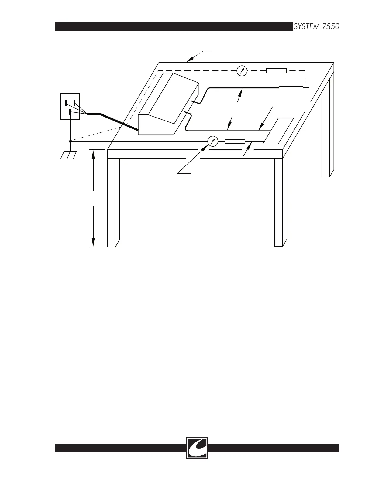
NON-CONDUCTIVE TABLE
200 OHMS
200 OHMS
.5 METER
.25 METER
RF AMMETER
(2 PLACES)
UNIT UNDER TEST
1 METER
EARTH
GROUND
Figure 3.2 IEC Method RF Leakage Test Setup
8-5
8.9 IEC RF Leakage Measurement
[Optional]
Due to the complex nature of the RF leakage
environment in a typical operating suite, the
International Electrotechnical Commission (IEC)
has adopted a repeatable test method to evaluate
high frequency leakage currents (alternate path
leakage currents) in electrosurgical generators in
an unambiguous fashion. The IEC test method
positions the Active and Return Electrode cables
a fixed distance from conductive surfaces. By this
method, the cable capacitance is fixed (or con
-
stant) and the resulting measurement is indicative
of the unit under test’s ability to minimize RF
leakage.
RF leakage occurs because a conductive path
provided by stray parasitic capacitance distrib
-
uted along the length of the Active and Return
Electrode cables to earth ground and other con
-
ductive mediums return surgical current to the
unit by means of an “alternate path”. Internal
unit capacitance and high frequency, high voltage
harmonic energy in the output voltage waveform
also contribute to the magnitude of alternate leak
-
age currents.
IEC has set a maximum limit for RF Leakage at
150mA when tested using the IEC setup. Most
of the modes available within the System 7550™
are well under this limit, however Spray and ABC
are typically at 130mA to 145mA. The IEC test
set up is as follows. Refer to Figure 8.2.
1. Attach the handcontrol accessory to the
Monopolar Handcontrol jack.
2. Connect a full length return electrode cable
to the Return Monitor receptacle on the System
7550™. The Patient Plate adapter may be used
for this test if the adapter is full length.
3. Extend the Active and return electrode cables
.5 meters from each other and 1 meter above the
floor. (Note: The RF leakage figure shown is the
IEC method. For consistency, it uses a table to
hold the cables at the proper distances. However,