2. Setup
COM-1PD(USB)H
11
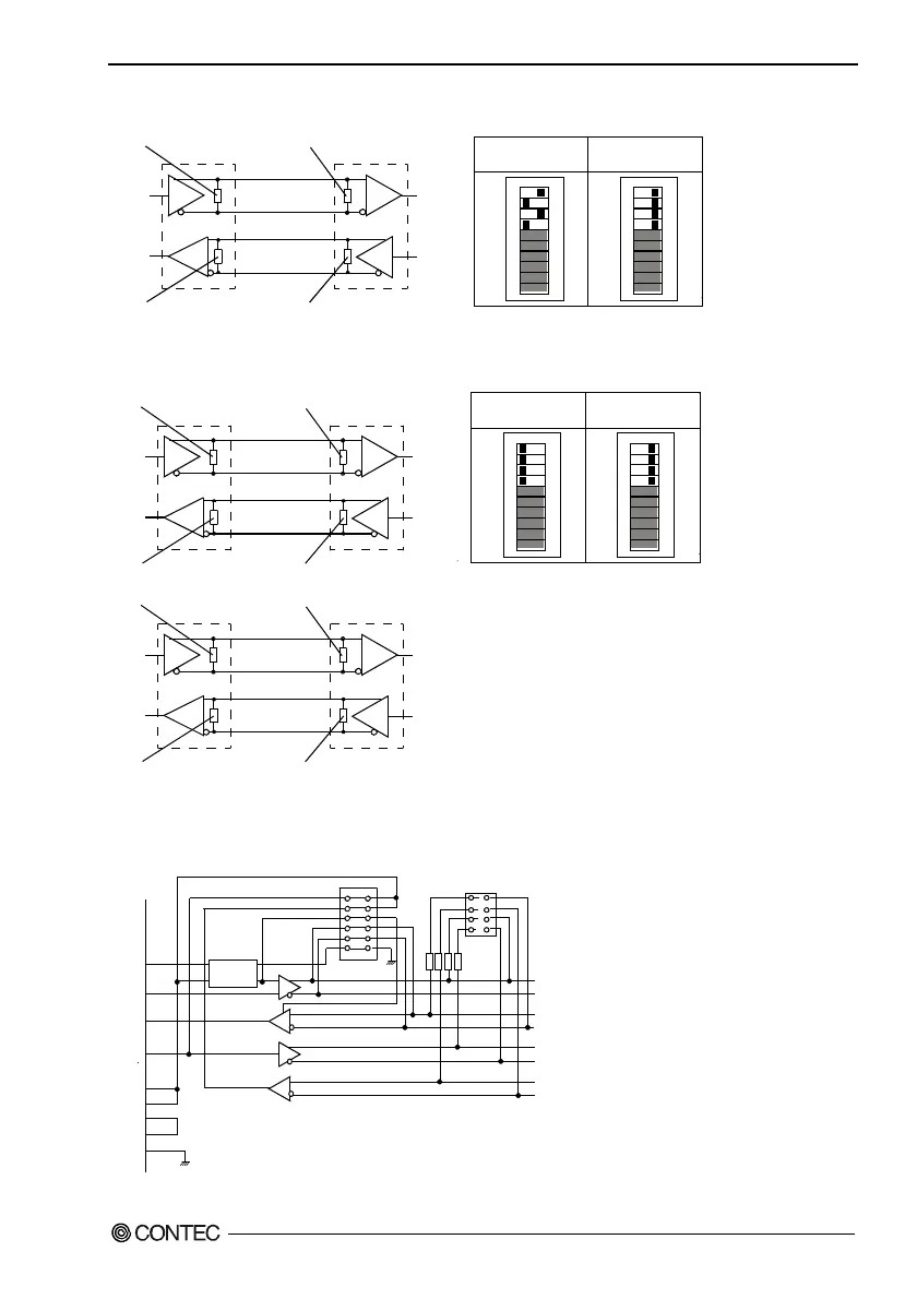
- Full-duplex
TxD
RxD
RxD
TxD
109
87654321
ON
109
87654321
ON
RTS
TxD
CTS
RxD
RTS
TxD
CTS
RxD
Terminator(bit9) Terminator(bit7)
Terminator(bit7)
Terminator(bit9)
Set the terminator of RTS, CTS to OFF.
Insert the
terminator
Not insert the
terminator
Figure 2.4. Loopbacking RTS and CTS
TxD
RxD
RxD
TxD
RTS
CTS
CTS
RTS
109
87654321
ON
109
87654321
ON
RTS
TxD
CTS
RxD
RTS
TxD
CTS
RxD
RTS
TxD
CTS
RxD
Terminator(bit9) Terminator(bit7)
Terminator(bit7) Terminator(bit9)
Terminator(bit10) Terminator(bit8)
Terminator(bit8) Terminator(bit10)
Insert the
terminator
Not insert the
terminator
Figure 2.5. Connecting RTS and CTS to external device
Illustrated below are the peripheral circuits for the data transmission mode setting and terminator setting
switches.
1
2
3
4
5
6
TxEN, SEL
RTS
TxEN
TxD
RxD
RTS
CTS
DCD
DSR
RI
04 TxD+
05 TxD-
08 RxD+
09 RxD-
02 RTS+
03 RTS-
07 CTS+
06 CTS-
DTR
7
8
9
10
Term in at or
100
Ω
Figure 2.6. Equivalent Circuits