3. Hardware Installations
26
SPC-8520-LA , SPC-8521-LA
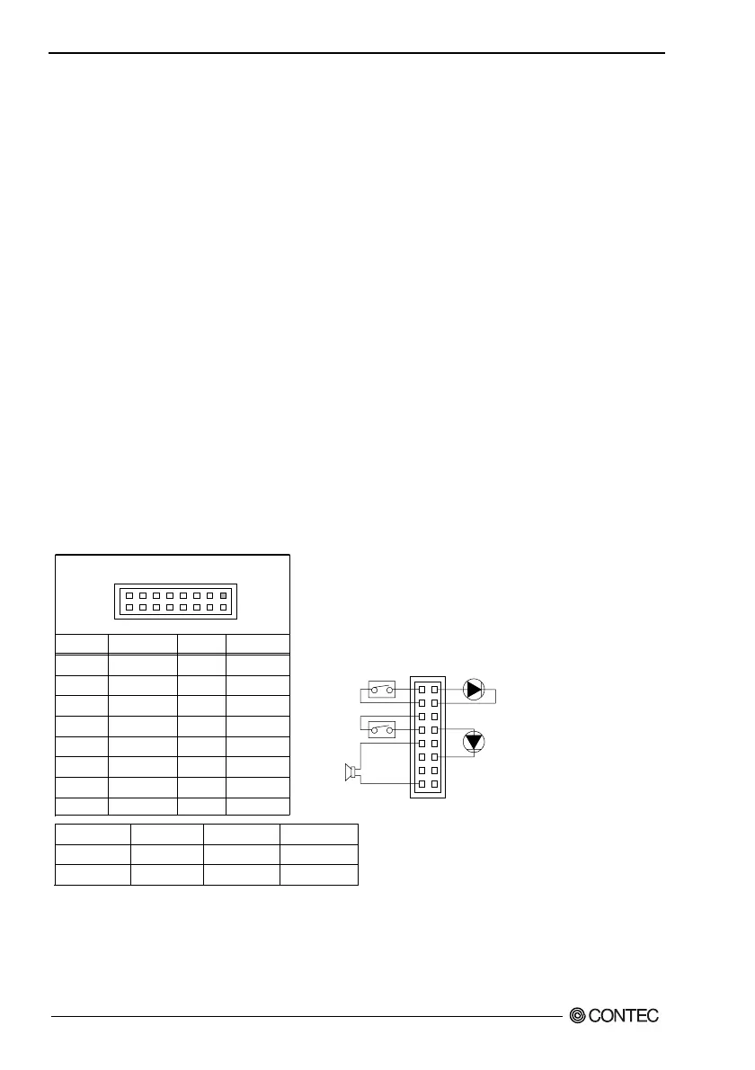
Front Panel Connector: CN1
This header can be connected to a front panel power switch. The front panel connector includes headers
for these I/O connections:
Power Button:
When the ATX power supply is used, this header connects power supply ON button.
Power LED:
This header is connected with a LED when turning on power to the computer.
Reset Button:
This header connects the reset button.
HDD LED:
This header is connected with a LED shown while being reading the data of the IDE hard disk drive or
writing it.
Speaker:
An external speaker can be installed in this product as an option. When the computer cannot use the
video interface, the speaker offers the error warning sound in POST. Moreover, because this speaker is
not connected with the audio subsystem, it is not possible to sound it by the output from the audio
subsystem.
Table 3.20. Front Panel Connector
Pin No.
1
3
5
7
9
11
13
15
Function
Power BT
GND
RESET
GND
Speaker+
N.C.
N.C.
Speaker-
Pin No.
2
4
6
8
10
12
14
16
Function
HDD LED+
HDD LED-
N.C.
Power LED+
N.C.
Power LED-
N.C.
N.C.
Speaker
Reset Button
Power LED
9, 11, 13, 15
5, 7
8, 10, 12
Power Button
HDD LED
1, 3
2, 4
CN1
1
2
15
16
1
15
Power Switch
for ATX
Reset Switch
External Speaker
(Ex. 8Ω 0.25W)
HDD Active Indicator LED
Power LED