Commander SE User Guide
Issue Number 5 31
For further information on braking and braking resistor sizing, refer to the Commander
SE Advanced User Guide.
5.2 Control terminal connections
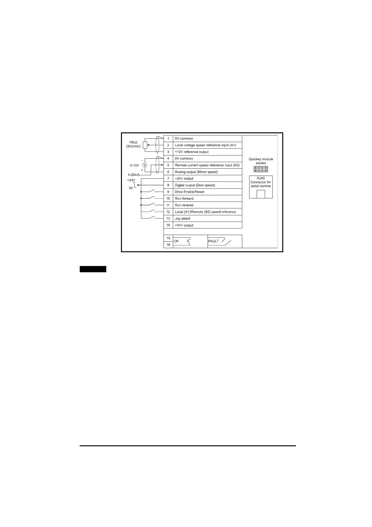
The terminal connections are shown in Figure 5.3. As default - in positive logic.
Maximum control terminal screw torque: 0.6 Nm (5.5 lb in)
Figure 5.3 Control terminal connections
The connection arrangement shown here illustrates how the terminals are
intended to be used. Screening of the analog signal wires is not essential, but
reduces the risk of electrical noise causing disturbance to the signals.
Where full EMC precautions are required, the guidelines in section 4.5.2 must
also be followed to ensure compliance with radio frequency emission limits.
This requires the use of one or more screened cables for all wiring to
terminals 1 to 14, with the screen bonded to the gland plate (ground). This
results in the 0V common terminal being connected to ground through the
cable screen.
Where it is required to keep 0V separate from ground, there are two
possibilities:
• Use a multi-core cable with overall screen, using one core for the 0V
connection. There is a slight risk of electrical noise affecting the
analog inputs.
• Use a double screened cable for the analog inputs, with the inner
screen connected to 0V and the outer screen to ground.
NOTE