Commander SE User Guide
30 Issue Number 5
5 Terminals
5.1 Power terminal connections
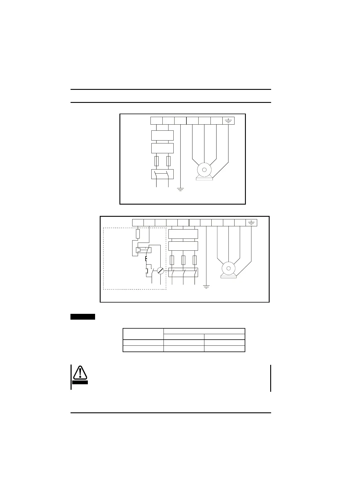
Figure 5.1 Commander SE Size 1 power terminal connections
Figure 5.2 Commander SE Size 2 to 4 power terminal connections
When a Commander SE Size 2 200 volt unit is used on single phase, use
terminalsL1andL2.
5.1.1 Thermal protection for an optional braking resistor
Figure 5.2 shows a typical circuit arrangement for braking resistor
protection. This thermal protection must disconnect the AC supply from the
Drive if the resistor becomes overloaded. (Do not use overload opening
contact in line with braking resistor).
L1 L2/N PE U V W
Optional
RFI filter
Optional
line reactor
Mains
Supply
Fuses
L1 L2/N
Supply
Ground
Motor
Motor
Ground
Circuit breaker
/Isolator
L1 L2
L2
L1
+
-
L3 PEDBR U V W
Optional RFI
filter
Optional
line reactor
Fuses
L3
Supply
Ground
Mains
Supply
Motor
Motor
Ground
Start/
Reset
Stop
Optional
Thermal
protection
device
Braking
Resistor
NOTE
Drive Size Maximum Power Terminal Screw Torque
Nm lb in
1&2
1
9
3&4
2
18
WARNING