*
41 M’Ax Advanced User Guide
www.controltechniques.com Issue Number: 4
Digital inputs connected to limit switches should be routed to these parameters if fast stopping is required at a limit. The drive will respond in
500µs(500µs digital input filter delay) and stop the motor with zero ramp rate (i.e. in current limit) if limit switch ramp is disabled (i.e.
parameter 2.05 Limit switch ramp disable is set to zero). If limit switch ramp is enabled the drive will stop the motor using the ramp rate set in
Forward deceleration ramp parameter 2.25 or Reverse deceleration ramp parameter 2.26.
The limit switches are direction dependant so that the motor can rotate in a direction that allows the system to move away from the limit
switch. The drive status will indicate “LSP” meaning Limit switch StoP active, until the system moves away from the limit switch.
The drive can operate from the following supplies as indicated by this parameter.
0-Mainpowerterminals
The drive power circuit, gate drives, control circuits and SLM module are using the main power terminals to derive their supplies. The drive
will operate normally. Parameters that are saved at power-down are saved when the supply is removed in this mode and a UU trip occurs.
1- 30V Control backup
Auxiliary back-up supply in operation.
The drive detects mains loss by comparing the DC bus voltage with the controlled stop enable DC bus level parameter 6.48.IftheDCbus
levelislessthanthevaluestoredinparameter6.48 thenacontrolledstopisrequested.DrivecontrolstherampratetokeeptheDCbuslevel
above the programmed level as close as possible to the required ramp rate. The drive will continue a controlled stop even if mains voltage is
restored.
This parameter indicates that the motor is being subject to controlled deceleration to a stop during failure of the AC supply.
0 = Controlled stop not active
1 = Controlled stop enabled
TheUVtriplevelis350VDC.
Refer to parameter 10.16.
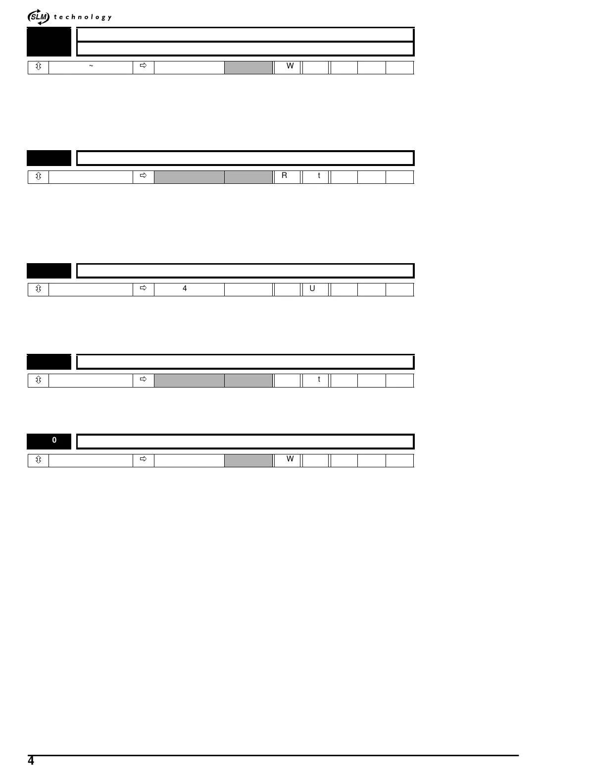
6.35 FORWARD LIMIT switch
6.36 REVERSE LIMIT switch
ô
0~1
ð
0 RW Bit
6.44 Active supply indicator
ô
0~1
ð
RO Bit
6.48 DC Bus threshold voltage
ô
0~600
ð
400 V RW Uni
6.49 Controlled stop enabled indicator
ô
0~1
ð
RO Bit
6.50 UV warning threshold
ô
0~600
ð
400 RW Uni