*
M’Ax Advanced User Guide 48
Issue Number: 4 www.controltechniques.com
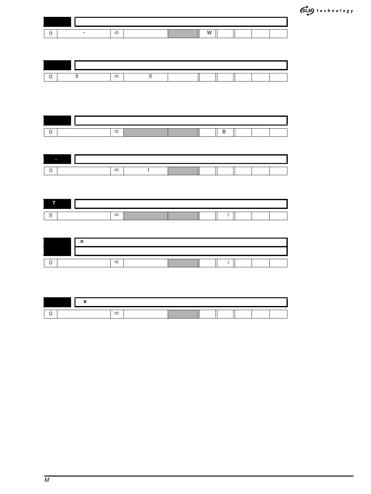
Setting this bit will cause the drive to adjust it's own scale factor such that the required maximum is reached at the input level at the time
calibration takes place. This parameter is cleared by the software when the calibration is complete.
This parameter affects the low speed performance and the speed of response to a changing speed demand. Low values give good dynamic
response but noisier operation at low speeds and high values give smooth low speed operation but less dynamic response. A compromise
must be made between low speed operation and good dynamic response.
After modification of this parameter the sample time is only changed when a reset or power down and back up again is carried out.
Indicates 1 if an AN (high precision) option module is fitted.
This parameter is the input scale factor (Counts / 250µs) for full analog input. This scale factor is automatically adjusted by the calibrate
routine, parameter 7.25. Default value is 227 which is nominal counts with 10V input.
This is the output of the V/F accumulator. Updated every 250µs.
The above two parameters are used for analog input ratio, when routed for Analog Reference input [Parameter 1.36], to achieve the last
niche of necessary maximum speed. The sampled analog input counts per every 250µS are scaled according to Maximum reference Clamp
[Parameter 1.06] and then multiplied by the numerator and divided by the denominator.
This parameter enables the ratio of Analog Reference input.
0-Disable
1 - Enable
7.25 Calibrate analog input 1 full scale
ô
0~1
ð
0 RW Bit
7.26 Analog input sample time
ô
0.250 ~ 4.000
ð
1.000 ms RW Uni R
7.52 AN option module fitted indicator
ô
0~1
ð
RO Bit
7.53 V/F scale
ô
±4096
ð
871 RW Uni
7.54 Filtered input
ô
±8192
ð
RO Uni
7.55 Analog input scaling numerator
7.56 Analog input scaling denominator
ô
±32367
ð
1 RW Uni
7.57 Analog input scaling enable
ô
0~1
ð
0 RW Bit