16 SM-Resolver User Guide
www.controltechniques.com Issue Number: 4
5.2 Solutions Module set-up
Action Detail
Before power-up
Ensure:
• Drive enable signal is not given (terminal 31)
• Solutions Module is fitted in appropriate slot
• Resolver is connected to the SM-Resolver
Power-up the drive
Ensure:
• Encoder Phase Error Detect is disabled (Pr
3.40
= 0) to prevent Enc2 trip
• Module error detectionis set-up as required (Pr
x.17
)
• Drive displays ‘inh’
If the drive trips, see Chapter 7 Diagnostics on page 31.
Slot identification
Identify which Solutions Module slot and associated menu are being used:
• Slot 1 – Menu 15
• Slot 2 – Menu 16
• Slot 3 – Menu 17
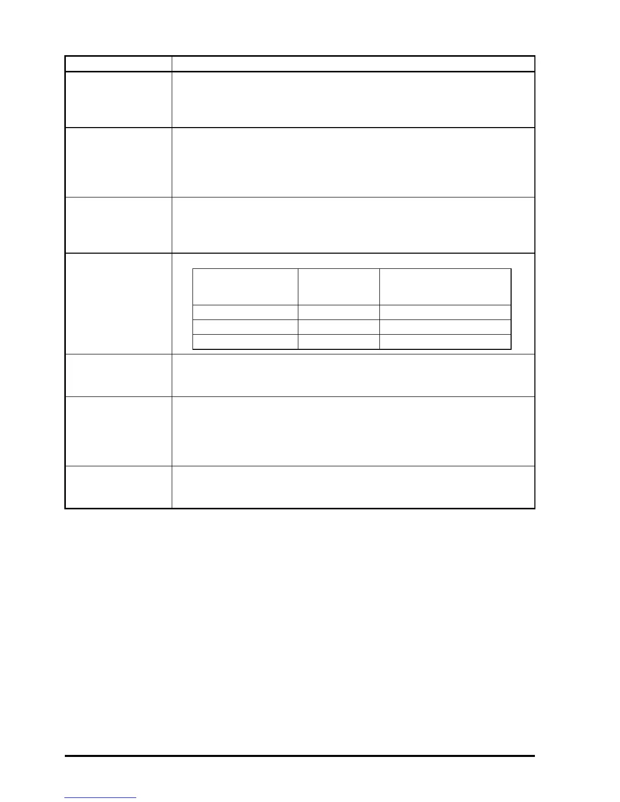
Set-up the operating
resolution and
variable maximum
speed limit
Enter the equivalent number of lines per revolution in Pr x.10:
Set-up resolver
excitation voltage
Set-up the correct excitation voltage for resolver:
• Turns ratio 3:1 (6V rms excitation), set Pr x.13 = 0
• Turns ratio 2:1 (4V rms excitation), set Pr x.13 = 2
Set-up the resolver
number of poles
Set-up the resolver number of poles:
• 2-pole set Pr x.15 = 0 (default setting)
• 4-pole set Pr x.15 = 1
• 6-pole set Pr x.15 = 2
• 8-pole set Pr x.15 = 3
Enable SM-Resolver
Enable the SM-Resolver as the drive position / speed feedback by setting
Pr 3.26 to Slot1 (1), Slot2 (2) or Slot3 (3) depending on the location of the
Solutions Module.
Max speed of motor
(2-pole resolver)
Operating
resolution
Equivalent resolution in
encoder lines per
revolution (Pr x.10)
0 to 3,300 rpm 14 bit 4,096
3,300.1 to 13,200 rpm 12 bit 1,024
13,200.1 to 40,000 rpm 10 bit 256