SM-Resolver User Guide 7
Issue Number: 4 www.controltechniques.com
3Introduction
3.1 Features
The SM-Resolver provides an interface for a resolver to be connected to the Unidrive
SP, to be used as position and speed feedback for the drive. The SM-Resolver also
provides a simulated quadrature encoder output.
All three Solutions Module slots can simultaneously accommodate a SM-Resolver,
however, only one of the three can be used to provide speed/position feedback at any
given time (see NOTE above).
Figure 3-1 SM-Resolver
3.2 Solutions Module identification
The SM-Resolver can be identified by:
1. The label located on the underside of the Solutions Module.
2. The colour coding across the front of the Solutions Module. All Unidrive SP
Solutions Modules are colour coded, with the SM-Resolver being light blue.
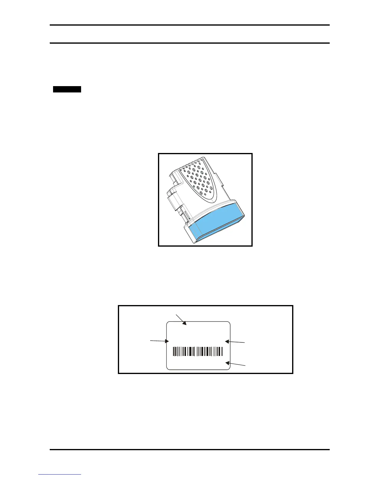
Figure 3-2 SM-Resolver label
3.2.1 Date code format
The date code is split into two sections: a letter followed by a number.
The letter indicates the year, and the number indicates the week number (within the
year) in which the Solutions Module was built.
The letters go in alphabetical order, starting with A in 1990 (B in 1991, C in 1992 etc.).
Example:
A date code of L35 would correspond to week 35 of year 2002.
The SM-Resolver will only provide speed and position feedback when it is selected as
the source of the drive speed/position feedback. Hence the SM-Resolver does not
function when the drive is operating in open-loop mode. Similarly, it is not possible to use
a resolver as a speed/position reference.
NOTE
SM-Resolver
Issue: 0
STDJ41
Ser No : 3000005001
Solutions Module
name
Customer
and date code
Serial number
Issue
number