SM-Resolver User Guide 9
Issue Number: 4 www.controltechniques.com
3.5 Operation of a resolver
A resolver is a rotating transformer that produces output voltages on a pair of SIN and
COS secondary windings. When an excitation voltage is applied to the primary winding
and the resolver shaft is rotated, amplitude-modulated voltage waveforms appear on the
secondary windings, where the excitation voltage acts as a carrier for the modulation. In
addition, on each secondary, the phase of the carrier voltage is reversed twice every
revolution.
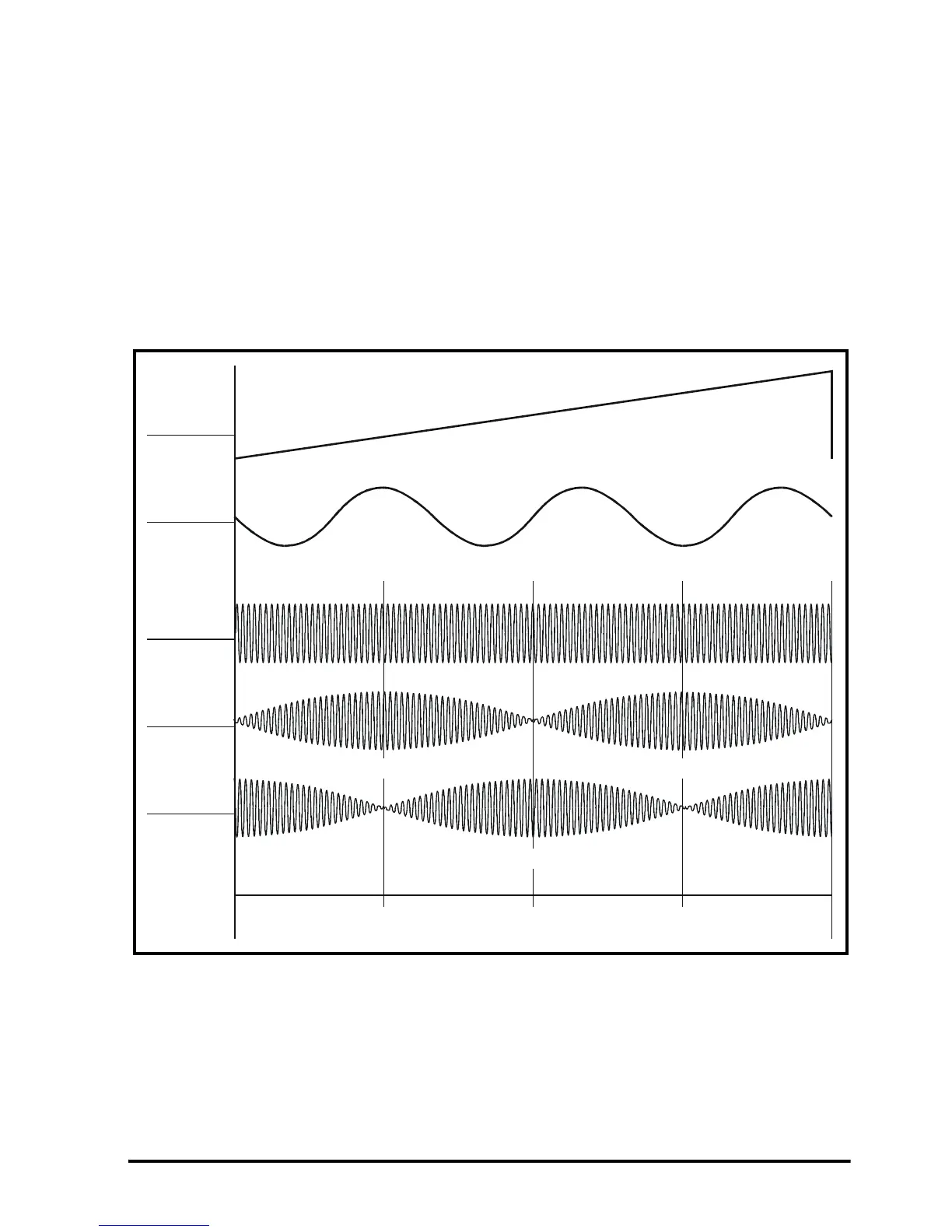
Figure 3-3 shows the relationships between the resolver position and the SIN and COS
outputs, as well as the phase reversals in the carrier waveforms for forward rotation (for
a clearer indication of the phase reversals, see Figure 3-4). Figure 3-3 also shows the
waveform of the U motor phase for a six-pole motor when the motor and resolver are
aligned for zero phase offset.
Figure 3-3 Sine and Cosine modulation on the secondary windings
3.5.1 Direction of rotation
Forward rotation is defined as follows:
Motor
Phase sequence: U V W
Resolver
COS modulation leads the SIN modulation (by 90°) (see Figure 3-4)
Resolver
position
SIN
secondary
COS
secondary
Zero
osition
180
o
90
o
270
o
Carrier with excitationin phase
Excitation
(primary)
Motor
U phase
Carrier with excitationin anti-phase
Carrier with excitationin anti-phaseCarrier
with excitation
in phase Carrier
with excitation
in phase