SM-Resolver User Guide 11
Issue Number: 4 www.controltechniques.com
4 Installing the SM-Resolver
4.1 Solutions Module slots
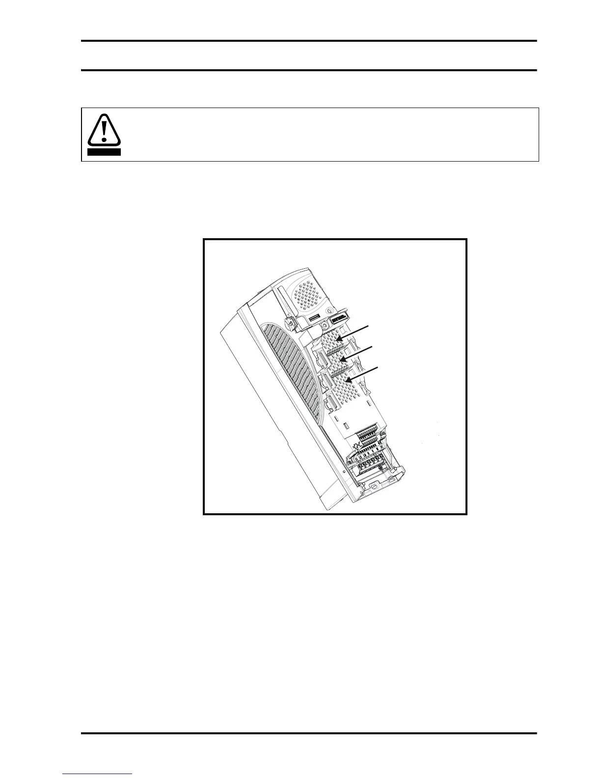
There are three slots available, which the Solutions Module can be plugged into as
shown in Figure 4-1. The Solutions Module can be plugged into either one of these, but
it is recommended that slot 3 be used for the first Solutions Module then slot 2 and slot
1. This ensures maximum mechanical support for the Solutions Module once fitted.
Figure 4-1 Location of slots 1, 2 and 3 on the Unidrive SP
4.2 Installation
1. Before installing the SM-Resolver in the Unidrive SP, ensure the AC supply has
been disconnected from the drive for at least 10 minutes.
2. Ensure that both the +24V, and +48V backup power supplies are disconnected from
the drive for at least 10 minutes if used.
3. Check that the exterior of the SM-Resolver is not damaged, and that the multi-way
connector is free from dirt and debris.
4. Do not install a damaged or dirty SM-Resolver in the drive.
5. Remove the terminal cover from the drive. (For removal / re-fitting instructions, see
Unidrive SP Solutions Module Installation Sheet provided with the Solutions
Module.)
6. Position the drive connector of the SM-Resolver over the connector of the
appropriate slot in the drive and push downwards until it locks into place.
Before installing the SM-Resolver, refer to Chapter 2 Safety information on page 5.
WARNING
Solutions Module
slot 1 (Menu 15)
Solutions Module
slot 2 (Menu 16)
Solutions Modul