12 SM-Resolver User Guide
www.controltechniques.com Issue Number: 4
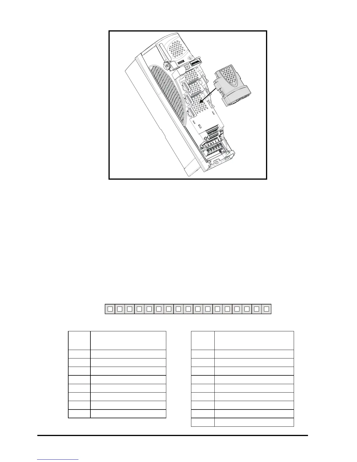
Figure 4-2 Fitting the SM-Resolver
7. Re-fit the terminal cover to the drive. (For removal / re-fitting instructions, see
Unidrive SP Solutions Module Installation Sheet provided with the Solutions
Module.)
8. Connect the AC supply to the drive.
9. Set Pr 0.49 to L2 to unlock read only security.
10. Check that Menu 15 (slot 1), 16 (slot 2), or 17 (slot 3) parameters are now available.
11. Check that Pr 15.01, Pr 16.01 or Pr 17.01 shows the correct code for the SM-
Resolver (code = 101).
12. If the checks in steps 10 and 11 fail, either the SM-Resolver is not fully inserted, or
the Solutions Module is faulty.
13. If a trip code is now present refer to Chapter 7 Diagnostics on page 31.
4.3 Terminal descriptions
Figure 4-3 SM-Resolver terminals
Table 4.1 SM-Resolver terminal descriptions
Term Simulated encoder
output connections
Term Resolver connections
1A 9SIN LOW
2 A\ 10 SIN HIGH
30V 11COS LOW
4 B 12 COS HIGH
5 B\ 13 REF HIGH (excitation)
6 0V 14 REF LOW (excitation)
7 Z 15 0V
8Z\ 160V
17 0V
12345678910 11 12 13 14 15 16 17