SM-Resolver User Guide 29
Issue Number: 4 www.controltechniques.com
Pr x.24 = Pr 3.29
Encoder simulation output is derived from the drive encoder port via hardware from the
A, B and Z inputs. The drive encoder signals must be digital and not SINCOS. No ratio
is possible, therefore Pr x.25 has no effect.
If Pr x.24 has any value than those above the encoder simulation outputs are not active.
Pr x.29 and Pr x.30 are duplicates of Pr x.04 and Pr x.05 respectively.
This Solutions Module does not have its own freeze input, therefore the freeze input
must come from a SM-Applications or SM-Universal Encoder Plus. The freeze data is
processed every 4ms x number of dumb modules fitted. If a freeze has occurred and the
freeze flag (Pr x.39) is zero, the position is stored in Pr x.36 and the freeze flag is set.
The freeze flag must be reset by the user before the next freeze event is stored. This
function is only active with 2 pole resolvers.
At power-up Pr x.45 is initially OFF (0), but is set to On (1) when the SM-Resolver can
provide position feedback. Pr x.45 then remains at On (1) whilst the drive is powered-
up.
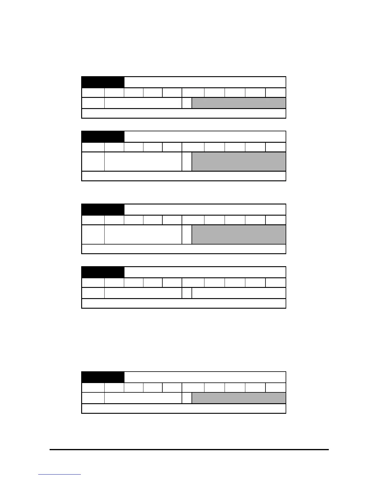
x.29 Non-marker reset revolution counter
RO Uni NC PT
Ú
0 to 65,535 revolutions
Ö
Update rate: 4ms x number of dumb modules
x.30 Non-marker reset position
RO Uni NC PT
Ú
0 to 65,535 (1/2
16
ths of a
revolution)
Ö
Update rate: 4ms x number of dumb modules
x.36 Freeze position
RO Uni NC PT
Ú
0 to 65535 (1/2
16
ths of a
revolution)
Ö
Update rate: 4ms x number of dumb modules
x.39 Freeze flag
RW Bit NC
Ú
OFF (0) or On (1)
Ö
OFF (0)
Update rate: 4ms x number of dumb modules
x.45 Position feedback initialised
RO Bit NC PT
Ú
OFF (0) or On (1)
Ö
Update rate: Background write