Safety
Information
Product
Information
Mechanical
Installation
Electrical
Installation
Getting
Started
Menu 0
Running
the motor
Optimisation Macros
Advanced
Parameters
Technical
Data
Diagnostics
UL Listing
Information
Unidrive User Guide 55
Issue Number: 9 www.controltechniques.com
The output voltage at terminal 13 is 5V when Pr 3.23 is set at 0 (default).
When Pr 3.23 is set at 1, the output voltage will become 15V. This could
damage encoders that require a 5V supply.
Termination resistors should be disabled by setting Pr 3.24 to 1 if the
encoder output is 15V.
This terminal is connected internally to terminal 8 of the signal connector
Connect only one of these terminals to a motor thermistor. Analog input
3 must be in thermistor mode, Pr 7.15 = th.Sc (9) or th (10).
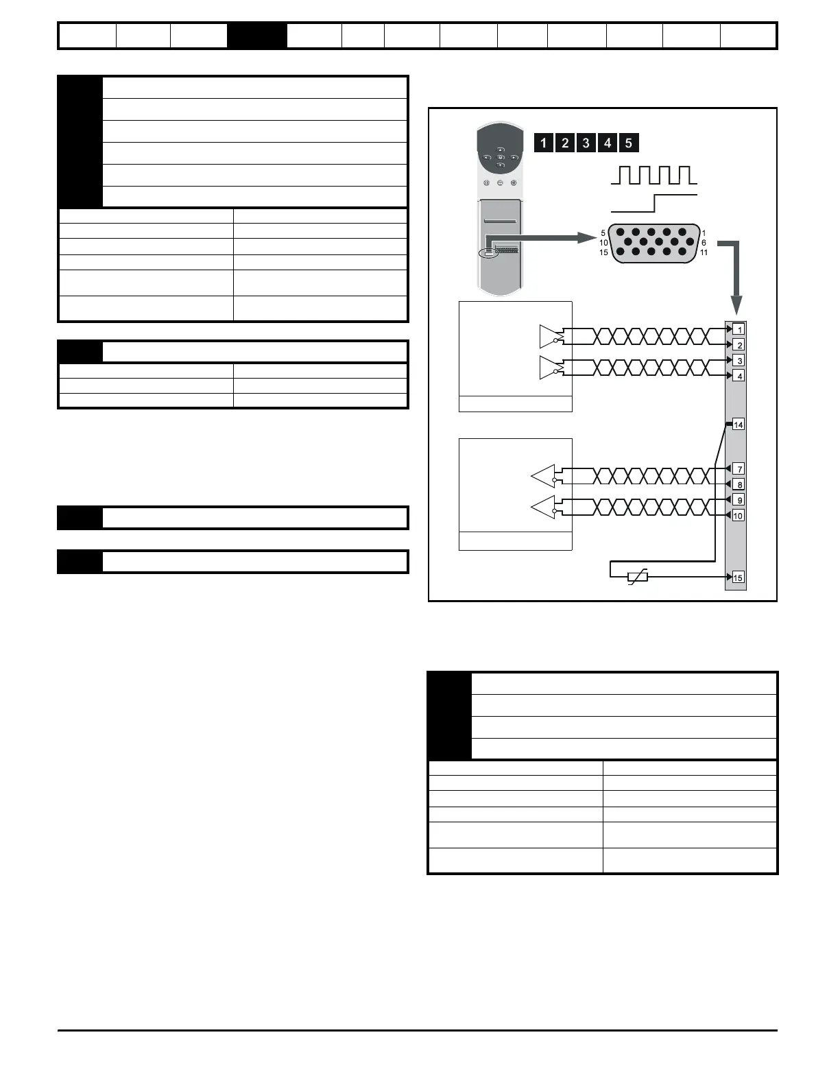
4.10.2 Frequency and direction connections
Figure 4-18 Frequency and direction connections and alternative
motor-thermistor connections
For encoder cable screening, see section 4-10 Feedback cable, twisted
pair on page 47.
Description of the frequency and direction connections
7 Phase channel U
8 Phase channel U\
9 Phase channel V
10 Phase channel V\
11 Phase channel W
12 Phase channel W\
Type EIA422 differential receivers
Maximum data rate 250kHz
Line termination components
120
Ω
Line loading 1 unit load
Absolute maximum applied voltage
relative to 0V
+15V to -10V
Absolute maximum applied differential
voltage
±25V
13 Encoder supply
Supply voltage +5.15V or +15V (selected by Pr 3.23)
Voltage tolerance ±2%
Nominal output current 300mA
14 0V common
15 Motor thermistor input
1 Frequency input FIN
2 Frequency input FIN\
3 Direction input DIN
4 Direction input DIN\
Type EIA422 differential receivers
Maximum data rate 250kHz
Line termination components
120
Ω (switchable using Pr 3.24)
Line loading 1 unit load
Absolute maximum applied voltage
relative to 0V
±15V
Absolute maximum applied differential
voltage
±25V
Encoder connector
Female 15-way D-type
Slave
Master
Frequency
reference
Direction
reference
Frequency
reference
Direction
reference